User equipment for wireless communication, and method and device in base station
A technology for wireless communication and user equipment, which is applied in the field of communication between air terminals and ground terminals, and can solve problems such as rapid changes in interference that cannot be solved.
- Summary
- Abstract
- Description
- Claims
- Application Information
AI Technical Summary
Problems solved by technology
Method used
Image

Examples
Embodiment 1
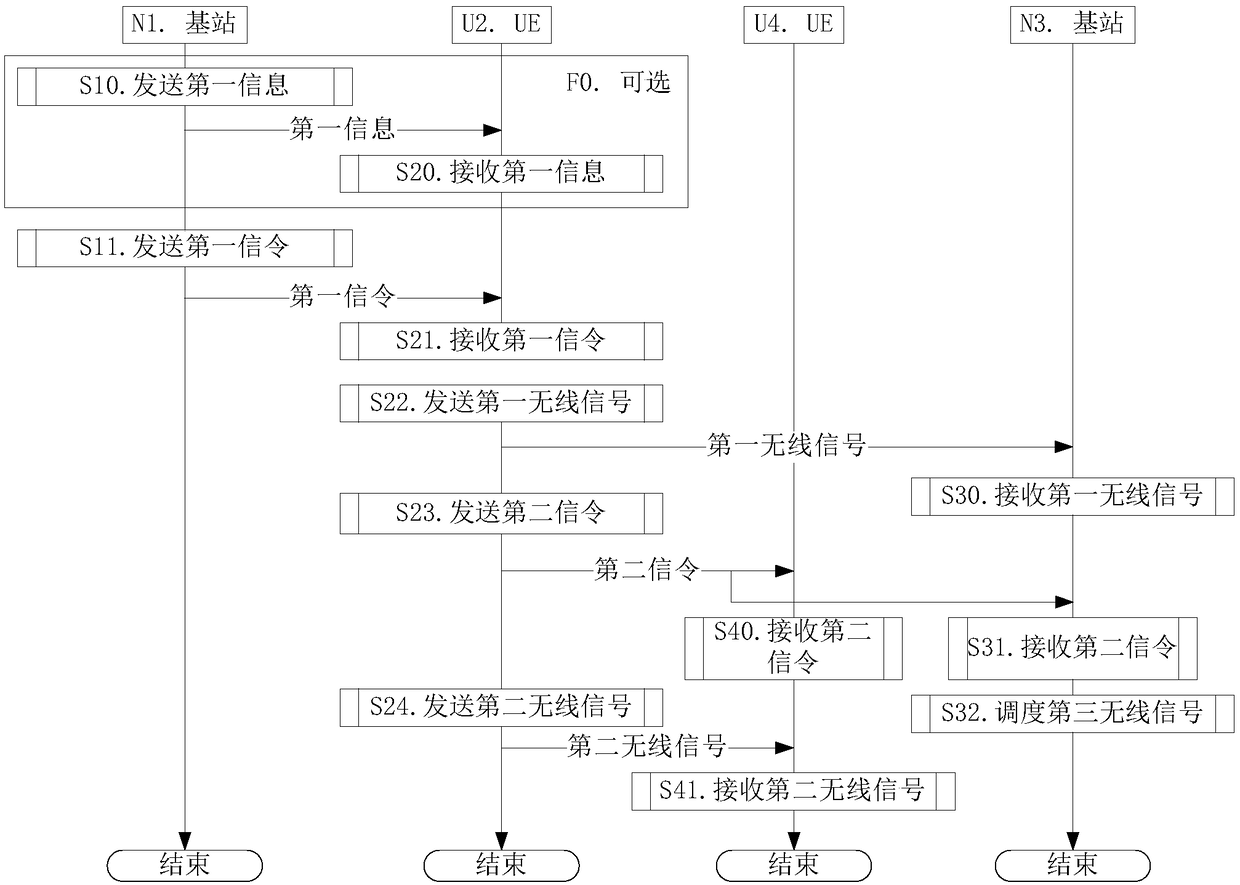
[0198] Embodiment 1 illustrates a flow chart of a first signaling transmission according to this application, as attached figure 1 Shown. Attached figure 1 Among them, the base station N1 is the maintenance base station of the serving cell of the UE U2, the base station N3 is the maintenance base station of the neighboring cell of the base station N1, and the UE U4 is the opposite UE of the UE U2. The step identified in box F0 is optional.
[0199] for Base station N1 , The first information is sent in step S10, and the first signaling is sent in step S11.
[0200] for UE U2 , Receiving the first information in step S20, receiving the first signaling in step S21, sending the first wireless signal in step S22, sending the second signaling in step S23, and sending the second wireless signal in step S24.
[0201] for Base station N3 , The first wireless signal is received in step S30, the second signaling is monitored in step S31, and the third wireless signal is scheduled in step S3...
Embodiment 2
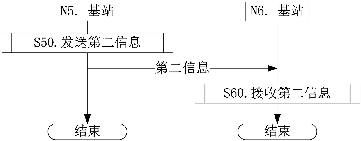
[0218] Embodiment 2 illustrates the flow chart of the second information transmission according to an embodiment of the present application, as shown in the attachment figure 2 Shown. Attached figure 2 , There is a backhaul link between base station N5 and base station N6.
[0219] for Base station N5 , In step S50, the second information is sent.
[0220] for Base station N6 , In step S60, the second information is received.
[0221] As a sub-embodiment, the backhaul link corresponds to one of {X2, S1} interfaces.
[0222] As a sub-embodiment, the base station N5 corresponds to the maintaining base station of the serving cell of the user equipment in the present invention, and the base station N6 corresponds to the maintaining base station of the neighboring cell of the serving cell of the user equipment in the present invention.
[0223] As a sub-embodiment, the base station N6 corresponds to the maintaining base station of the serving cell of the user equipment in the present in...
Embodiment 3
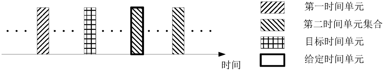
[0225] Embodiment 3 shows a schematic diagram of the sequence of the first signaling, the first wireless signal, and the second signaling. image 3 Shown. Attached image 3 Wherein, the first signaling is transmitted in a first time unit, the first wireless signal is transmitted in a target time unit, and the second signaling is transmitted in a second time unit set. The first time unit in the time domain in the second time unit set is a given time unit.
[0226] As a sub-embodiment, the target time unit corresponds to time unit #A, the given time unit corresponds to time unit #(A+K2), the A is a non-negative integer, and the K2 is a positive integer.
[0227] As a subsidiary embodiment of this sub-embodiment, the K2 is fixed.
[0228] As a subsidiary embodiment of this sub-embodiment, the K2 is configured through higher layer signaling.
[0229] As a subsidiary embodiment of this sub-embodiment, the K2 is explicitly indicated by the first wireless signal in this application.
[0230]...
PUM
 Abstract
Description
Claims
Application Information
 - R&D
- Intellectual Property
- Life Sciences
- Materials
- Tech Scout
- Unparalleled Data Quality
- Higher Quality Content
- 60% Fewer Hallucinations
Browse by: Latest US Patents, China's latest patents, Technical Efficacy Thesaurus, Application Domain, Technology Topic, Popular Technical Reports.
© 2025 PatSnap. All rights reserved.Legal|Privacy policy|Modern Slavery Act Transparency Statement|Sitemap|About US| Contact US: help@patsnap.com