Escapement speed regulation module of watch and application of escapement speed regulation module
A technology for speed regulation modules and watches, which can be used in escapement mechanisms, clocks, mechanically driven clocks, etc., and can solve problems such as not being suitable for installation at the same time
- Summary
- Abstract
- Description
- Claims
- Application Information
AI Technical Summary
Problems solved by technology
Method used
Image
Examples
Embodiment 1
[0038] Embodiment 1, the application when the escapement speed regulation module is installed on the assembly surface.
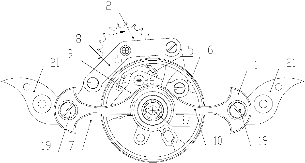
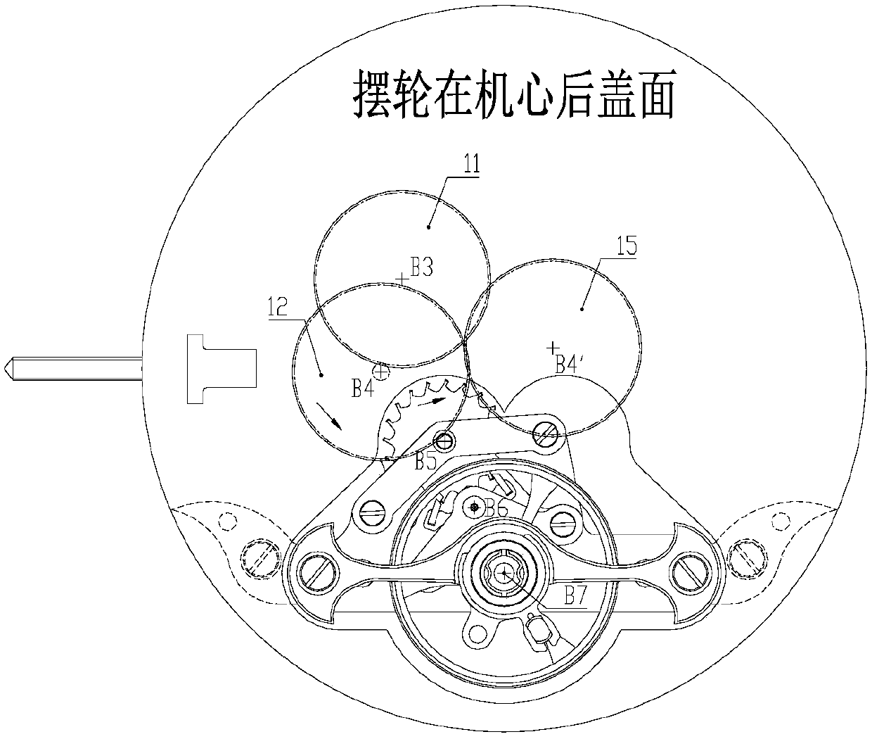
[0039] Such as image 3 , Figure 5 and Figure 9 As shown, the speed control module 1 is positioned with two positioning nails 18, and fixed with two fixing screws 20 through these two screw holes. combine image 3 and Figure 5 : B3 is the three-wheel piece 11, B4 is the four-wheel part 12, B4' is the intermediate wheel part 15, B5 is the escape wheel part 2 in the speed control module 1, and B6 is the escapement in the speed control module 1 The fork part 5, B7 is the balance wheel assembly 6 in the speed regulating module 1. The four-wheel sheet 13 is pressed together with the four-pinion shaft 14 to form the four-wheel component 12 . Two four-wheel pieces 13 are pressed together with the intermediate wheel shaft 16 to form the intermediate wheel component 15 . The three-wheel sheet 11 meshes with the four-pinion shaft 14 in the four-wheel part 12...
Embodiment 2
[0040] Embodiment 2, the application when the escapement speed regulation module is installed on the dial surface.
[0041] Such as Figure 4 and Figure 6Shown, in the figure: B3 place tricycle piece 11 meshes with the four pinion shaft 14 in the B4 place four-wheel part 12, the four-wheel piece 13 in the B4 place four-wheel part 12 and the intermediate wheel part 15 at B4' place The four-wheel piece 13 meshes, and the four-wheel piece 13 in the intermediate wheel part 15 at the B4' place meshes with the escape pinion 4 in the escape wheel part 2 at the B5 place.
[0042] After the movement without the speed regulating module 1 is turned over, the three-wheel piece 11 then rotates counterclockwise, and the four-wheel part 12 engaged with it then rotates clockwise, and the four-wheel part 15 meshes with the four-wheel part 12, so the intermediate wheel Part 15 turns counterclockwise. Such as image 3 As shown, the speed regulating module 1 is installed in the movement, bec...
Embodiment 3
[0043] Embodiment 3, the principle is the same as that of Embodiment 1 and Embodiment 2, and will not be repeated here. Now only the different parts are described, that is, the transmission between the four-wheel part 12 at B4 and the intermediate wheel part 15 at B4'. An even number of intermediate wheels can be added between them, so that the rotation direction of the intermediate wheel part 15 and the four-wheel part 12 are opposite, and the speed regulating module 1 can be freely assembled to the front and back of the machine without changing the other transmission structures of the movement. In the core, while other transmission mechanisms do not move, the installation of the watch movement is simplified.
PUM
 Abstract
Description
Claims
Application Information
 - R&D
- Intellectual Property
- Life Sciences
- Materials
- Tech Scout
- Unparalleled Data Quality
- Higher Quality Content
- 60% Fewer Hallucinations
Browse by: Latest US Patents, China's latest patents, Technical Efficacy Thesaurus, Application Domain, Technology Topic, Popular Technical Reports.
© 2025 PatSnap. All rights reserved.Legal|Privacy policy|Modern Slavery Act Transparency Statement|Sitemap|About US| Contact US: help@patsnap.com


