A lamp leg guide wire riveting device and a riveting method thereof

A lamp pin and riveting technology, which is applied in the direction of electrical components, circuits, connections, etc., can solve the problems of small riveting area and weak riveting, and achieve the effect of large riveting area, simple structure and small frictional resistance

Pending Publication Date: 2019-01-22
南京合力电光源设备制造厂
View PDF0 Cites 0 Cited by
  • Summary
  • Abstract
  • Description
  • Claims
  • Application Information

AI Technical Summary

Problems solved by technology

In the production process of LED fluorescent lamps, one end of the luminous strip needs to be welded with a guide wire, and the other end is welded with a driving circuit boa

Method used


Image

  • A lamp leg guide wire riveting device and a riveting method thereof
  • A lamp leg guide wire riveting device and a riveting method thereof
  • A lamp leg guide wire riveting device and a riveting method thereof

Examples


Embodiment Construction

[0021] In order to make the purpose, technical solutions and advantages of the embodiments of the present invention clearer, the technical solutions in the embodiments of the present invention will be clearly and completely described below in conjunction with the drawings in the embodiments of the present invention. Obviously, the described embodiments It is a part of the embodiments of the present invention, rather than all embodiments; based on the embodiments of the present invention, all other embodiments obtained by those of ordinary skill in the art without creative work, all belong to the protection scope of the present invention .

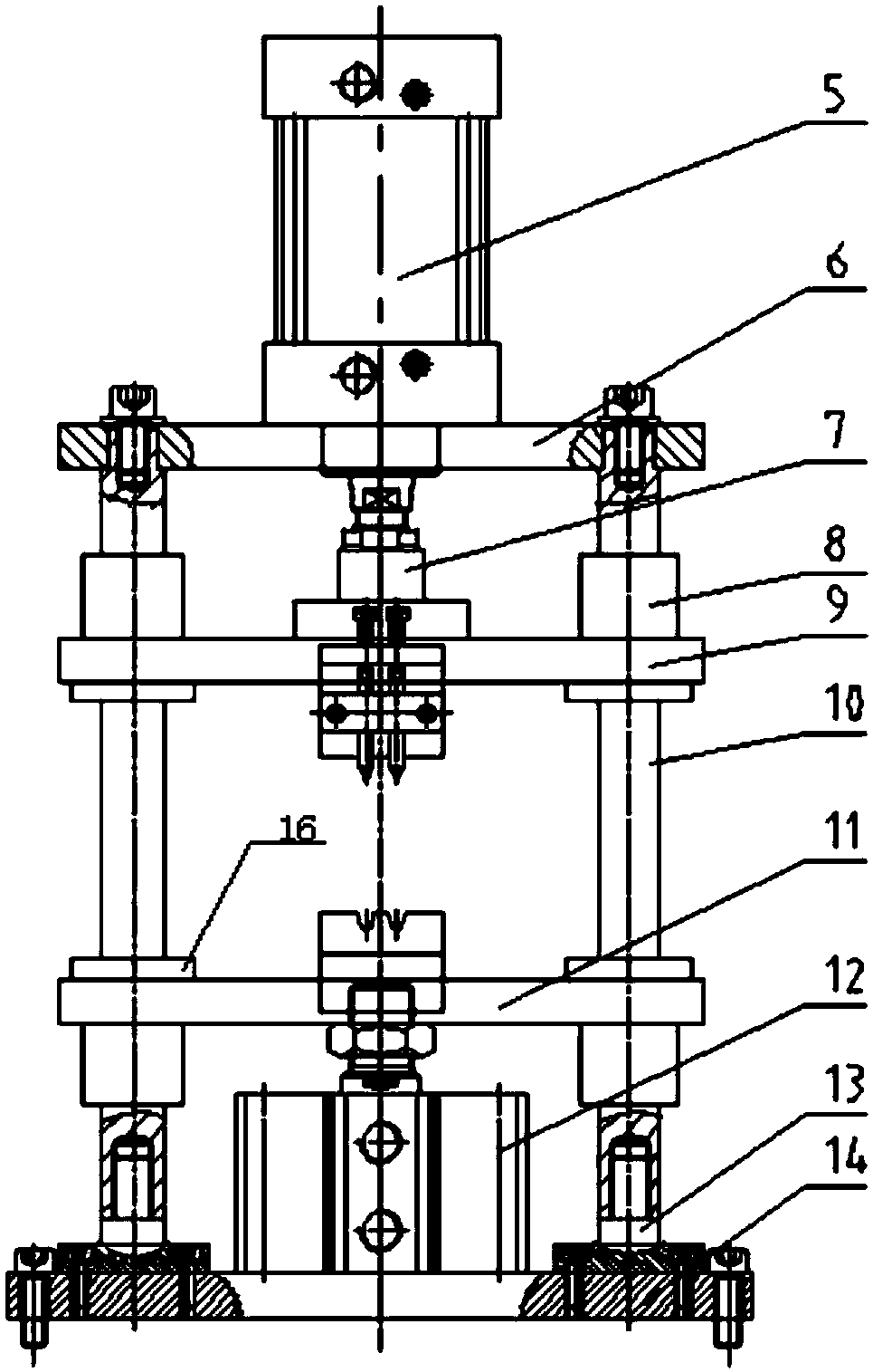
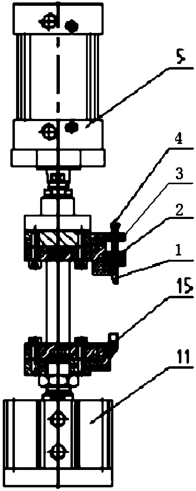
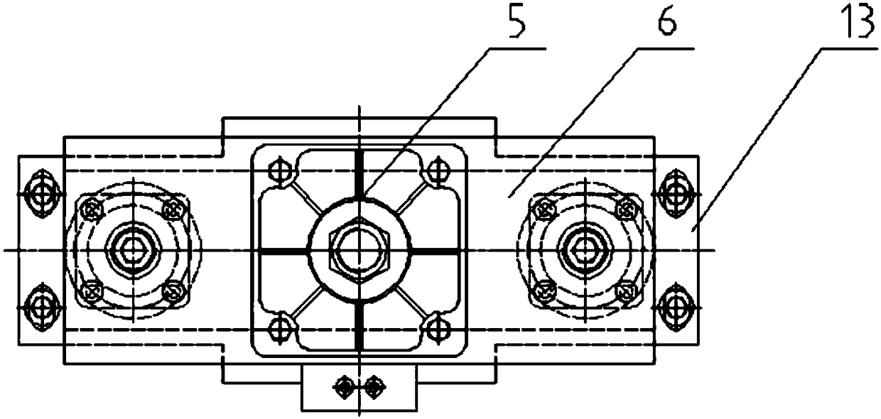
[0022] see Figure 1-4 , the present invention provides a technical solution: a lamp pin guide wire riveting equipment, including a bottom plate 14, the top of the bottom plate 14 is provided with a shaft seat 13, and the top of the shaft seat 13 is provided with two guide columns 10, the The top of the guide column 10 is provided with a t...


PUM


Abstract

The invention provides a lamp leg guide wire riveting device comprising a bottom plate. A shaft seat is arranged at that top of the bottom plate, two guide columns are arranged at the top of the shaftseat. A top plate is arranged at the top of a guide column, A low end of that guide post is slidably connected with a second linear bear, A slide plate is arranged between the second linear bearings,a lifting cylinder arranged at the top of the bottom plate is connected to the bottom of the slide plate, a first linear bearing is arranged at the top of the support plate on the guide post, an upper sliding plate is arranged between the first linear bearings, and a lower pressure cylinder is arranged at the top of the top plate. A square rivet needle is adopted, the rivet point is of a long groove type, the riveting area is large, the riveting guide wire is firmly fixed in the lamp leg aft riveting, the guide column and the first linear bearing are matched with the second linear bearing, the friction resistance is small, the guide property is good, the lifting cylinder and the lower pressure cylinder are adopted, the structure is simple, and automatic riveting can be realized.

Description

technical field [0001] The invention relates to the technical field of riveting equipment, in particular to a lamp pin guide wire riveting equipment and a riveting method thereof. Background technique [0002] LED fluorescent lamps, commonly known as straight tube lamps, are a substitute for traditional fluorescent tubes, which are reflected in two aspects of energy saving and environmental protection. In the production process of LED fluorescent lamps, one end of the luminous strip needs to be welded with a guide wire, and the other end is welded with a driving circuit board. The riveting is inside the lamp foot. The current riveting method is to use a round riveting needle for riveting. The riveting area is small and the riveting is not firm. Contents of the invention [0003] The invention overcomes the deficiencies in the prior art, and the technical problem to be solved is: to provide a lamp pin guide wire riveting device and a riveting method thereof. [0004] In o...

Claims


Application Information

Patent Timeline
IPC IPC(8): H01R43/048
CPCH01R43/048
Inventor 高国干葛盼路
Owner 南京合力电光源设备制造厂
Why Eureka
Try Eureka