Assembling positioning mechanism and method of draught fan impeller blades and draught fan impeller chassis

A technology of fan impeller and positioning mechanism, applied in auxiliary devices, auxiliary welding equipment, welding/cutting auxiliary equipment, etc., can solve the problems of high operator requirements, difficulty in ensuring the blade positioning angle, complicated operation, etc., to improve welding accuracy and quality, improve assembly and welding efficiency, and ensure the effect of positioning consistency

Active Publication Date: 2019-01-25
FOSHAN GOOGOL AUTOMATION TECH
View PDF6 Cites 1 Cited by
  • Summary
  • Abstract
  • Description
  • Claims
  • Application Information

AI Technical Summary

Problems solved by technology

However, this method is not only complicated to operate and low in efficiency, but also has high requirements for the operator, and greatly reduces the efficiency of fan impeller production, and it is difficult to ensure the positioning angle of each blade on the chassis, which affects the welding accuracy and quality of the fan impeller

Method used


Image

  • Assembling positioning mechanism and method of draught fan impeller blades and draught fan impeller chassis
  • Assembling positioning mechanism and method of draught fan impeller blades and draught fan impeller chassis
  • Assembling positioning mechanism and method of draught fan impeller blades and draught fan impeller chassis

Examples


Embodiment

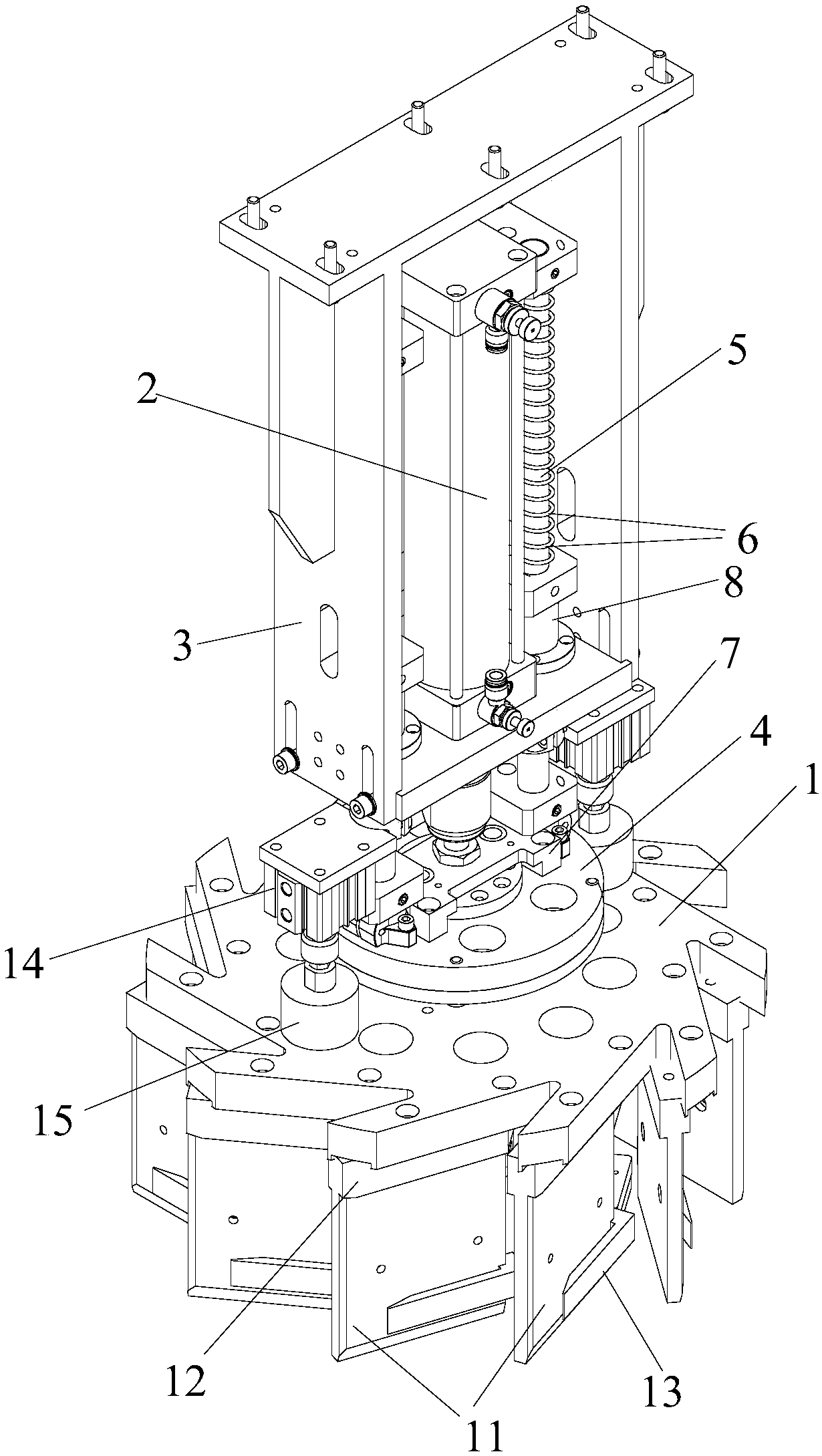
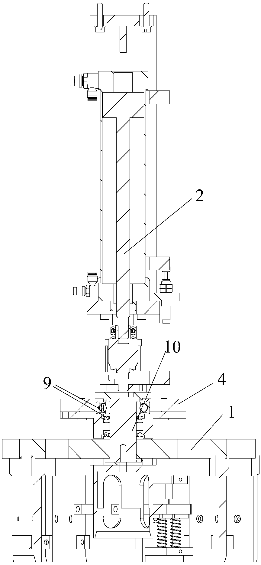
[0040] Such as Figure 1 to Figure 5 As shown, the assembly and positioning mechanism of the fan impeller blade and the fan impeller chassis of the present invention is characterized in that: comprising:

[0041]It is used to press and position the chassis 24 and be rotatable, and is used to correct the blade 23 and position it on the downward pressure positioning device on the chassis 24;

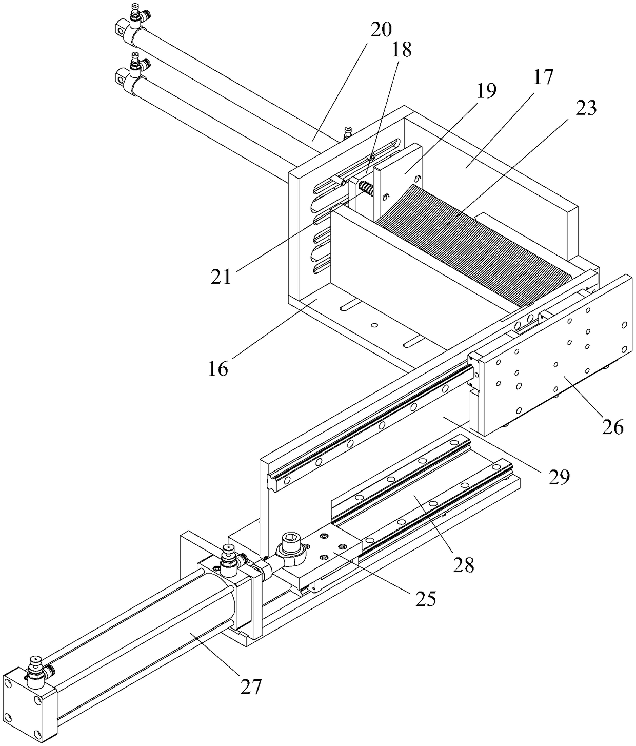
[0042] And it is used to arrange and push the blades 23 to the output station, and push the blades 23 of the output station to the push-down positioning device one by one;

[0043] Wherein, the pressing positioning device is located above the chassis positioning station, and includes a fixed mold 1 for correcting and positioning the blade 23 and a holding part for pressing the fixed mold 1 onto the chassis 24. The fixed mold 1 and the holding part Connected and located above the chassis positioning station, the fixed mold 1 is evenly equipped with welding stations for the blades 23 and th...


PUM


Abstract

The invention provides an assembling positioning mechanism and method of draught fan impeller blades and a draught fan impeller chassis. The assembling positioning mechanism comprises a pressing positioning device and a blade pushing device; the pressing positioning device is used for pressing, holding and positioning the chassis, making the chassis rotate, and correcting the blades and positioning the blades on the chassis, the blade pushing device is used for arraying the blades and pushing the blades to an output working station, and pushing the blades on the output working station to the pressing positioning device piece by piece; the pressing positioning device is located above a chassis positioning working station and comprises a fixed mould and a pressing holding part, wherein the fixed mould is used for correcting and positioning the blades, and the pressing holding part is used for pressing the fixed mould on the chassis; the fixed mould and the pressing holding part are connected and located above the chassis positioning working station, the fixed mould is evenly provided with welding working stations of the blades and the chassis, and the number of the welding working stations is equal to that of the blades; the output working stations correspond to the welding working stations one to one. By the adoption of the assembling positioning mechanism and method of the draught fan impeller blades and the draught fan impeller chassis, not only can the assembling welding efficiency of the blades and the chassis be improved, but also the positioning uniformity of each blade and the chassis can be guaranteed, and thus the welding precision and quality of the blades and the chassis are improved.

Description

technical field [0001] The invention relates to the technical field of industrial welding, and more specifically relates to an assembly and positioning mechanism and method for fan impeller blades and fan impeller chassis. Background technique [0002] The fan impeller is a key component of the fan, and whether its structural setting is reasonable directly affects the overall performance of the fan. During the working process, the impeller of the fan rotates to drive the flow of gas, thereby realizing the discharge and delivery of gas. [0003] A fan impeller is a bladed disc consisting of a chassis, blades and a top cover. The chassis and the top cover are arranged in parallel, the number of blades is several and the blades are evenly distributed between the chassis and the top cover, and the two sides of the blades are fixedly connected to the chassis and the top cover respectively. In order to ensure the stability of the connection between the blade, the chassis and the...

Claims


Application Information

Patent Timeline
Patent Type & Authority Applications(China)
IPC IPC(8): B23K37/04B23K37/047
CPCB23K37/0426B23K37/047Y02E10/72
Inventor 胡国强杨凤莲刘泽裕
Owner FOSHAN GOOGOL AUTOMATION TECH
Why Eureka
Try Eureka