
Sheet metal part forming machine and method for manufacturing sheet metal part by utilizing sheet metal part forming machine

A sheet metal part and forming machine technology, which is applied in the field of sheet metal part forming machines and sheet metal parts making using sheet metal part forming machines, can solve the problems of high production cost, low operation efficiency, time-consuming and labor-intensive, etc.

Active Publication Date: 2019-01-25
LEKAI TECH SUZHOU
View PDF11 Cites 6 Cited by
  • Summary
  • Abstract
  • Description
  • Claims
  • Application Information

AI Technical Summary

Problems solved by technology

[0003] For the existing sheet metal parts of the box structure, it is usually necessary to cut the four corners of the sheet metal on a cutting machine, and then bend the four sides of the sheet metal on a bending machine for four times. The processing method is low in operation efficiency, time-consuming and labor-intensive, and the production cost is high

Method used


Image

  • Sheet metal part forming machine and method for manufacturing sheet metal part by utilizing sheet metal part forming machine
  • Sheet metal part forming machine and method for manufacturing sheet metal part by utilizing sheet metal part forming machine
  • Sheet metal part forming machine and method for manufacturing sheet metal part by utilizing sheet metal part forming machine

Examples


Embodiment Construction

[0021] In order to make the purpose, technical solutions and advantages of the embodiments of the present invention clearer, the technical solutions in the embodiments of the present invention will be clearly and completely described below in conjunction with the drawings in the embodiments of the present invention. Obviously, the described embodiments It is a part of embodiments of the present invention, but not all embodiments. Based on the embodiments of the present invention, all other embodiments obtained by persons of ordinary skill in the art without creative efforts fall within the protection scope of the present invention.

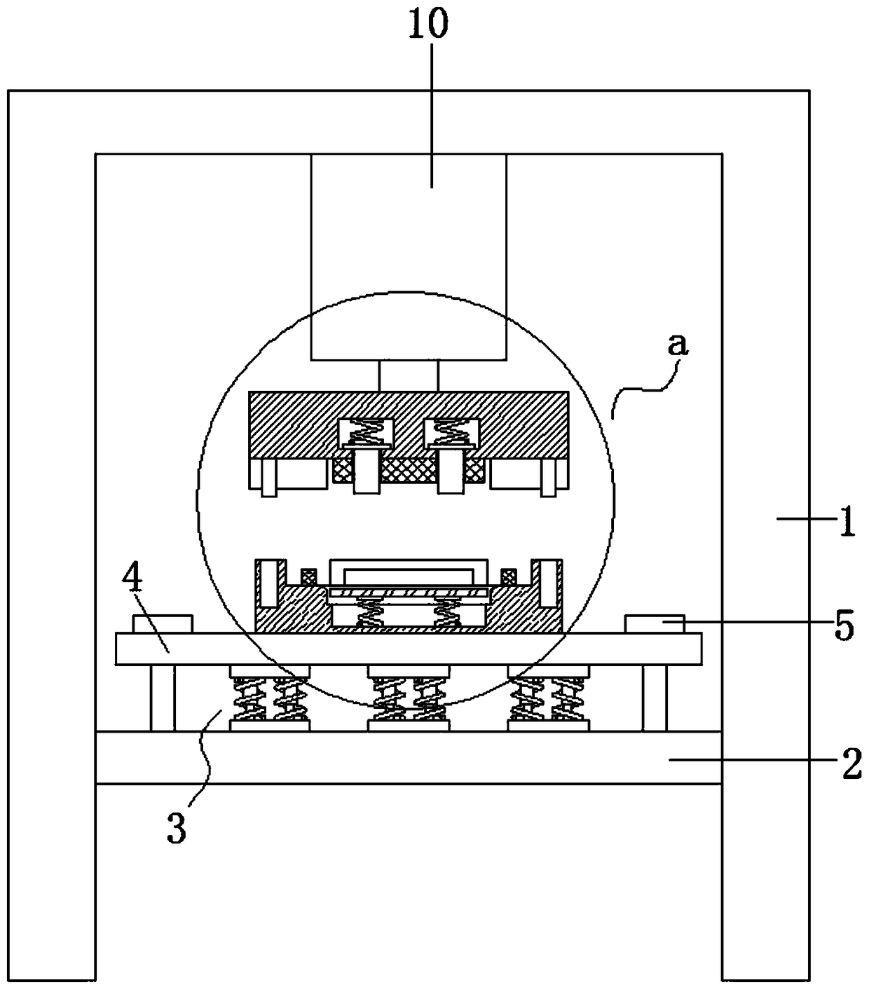
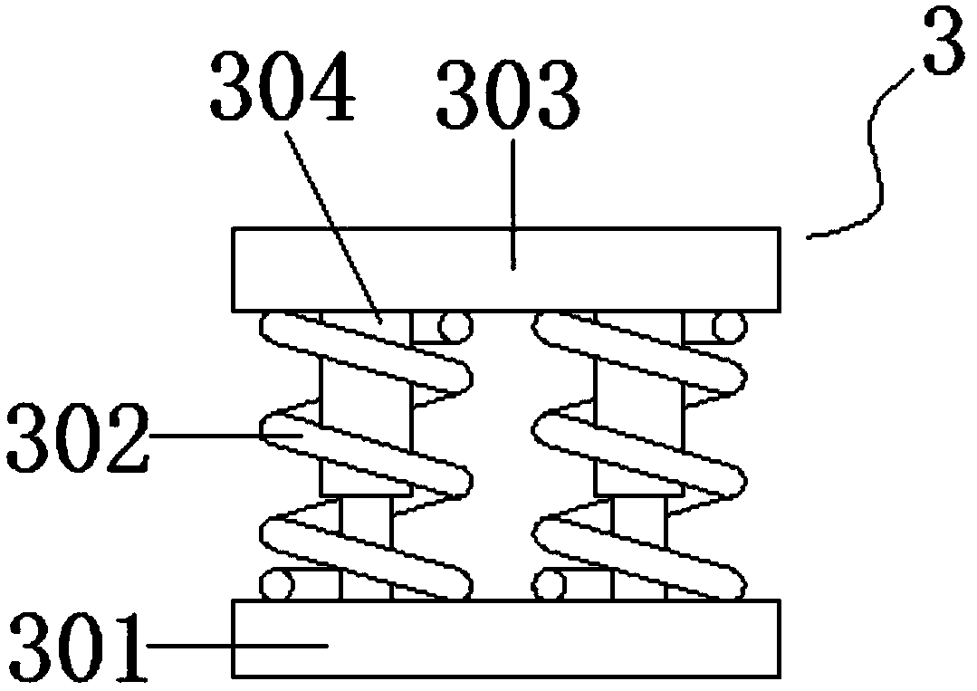
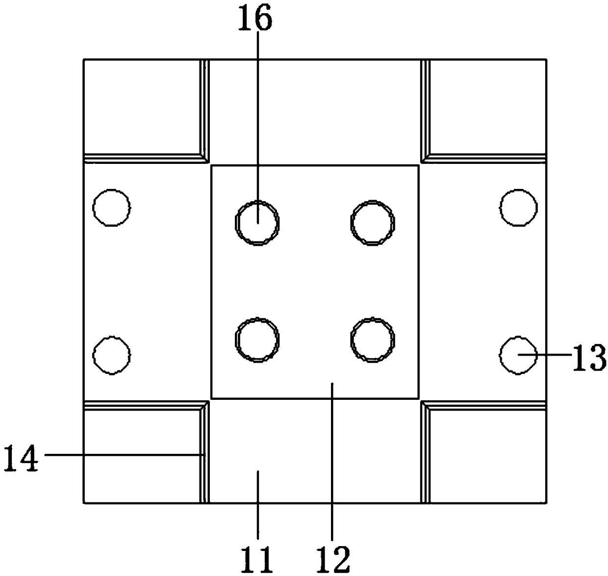
[0022] combine figure 2 , 3 , 4, 5, see figure 1 : A sheet metal forming machine, comprising a frame 1, the inside of the frame 1 is provided with a fixed plate 2, the top of the fixed plate 2 is evenly provided with a shock absorbing mechanism 3, and the top of the shock absorbing mechanism 3 is provided with a support plate 4, The left and r...


PUM


Abstract

The invention relates to the technical field of sheet metal processing, and particularly relates to a sheet metal part forming machine and a method for manufacturing a sheet metal part by utilizing the sheet metal part forming machine, which comprises a frame, wherein a fixed plate is arranged inside the frame, the top of the fixed plate is evenly equipped with a damping mechanism, the top of thedamping mechanism is provided with a supporting plate, the left side and the right side of the top of the supporting plate are respectively provided with a limiting bolt, the lower end of the limitingbolt penetrates through the supporting plate and is fixedly connected with the fixing plate, the top of the supporting plate is provided with a lower die, the tops of bosses on the left side and theright side of the lower die are provided with positioning column matching holes, the top of the lower die is provided with a stamping groove, the front, rear, left and right side of the stamping groove are respectively provided with threaded holes, the four corners of the stamping groove are provided with right-angle cutter matching grooves. The invention has the advantages of novel in design andconvenient to use, the sheet metal forming machine can not only cut the four corners of the sheet metal, but also can realize the simultaneous bending of four sides of the sheet metal plate, greatly improves the processing efficiency of the sheet metal part, and is suitable for popularization and use.

Description

technical field [0001] The invention relates to the technical field of sheet metal processing, in particular to a sheet metal forming machine and a method for manufacturing sheet metal using the sheet metal forming machine. Background technique [0002] Sheet metal parts refer to parts made of metal sheets (usually below 6mm) into consistent shapes. [0003] For the existing sheet metal parts of the box structure, it is usually necessary to cut the four corners of the sheet metal on a cutting machine, and then bend the four sides of the sheet metal on a bending machine for four times. The processing method is low in operation efficiency, time-consuming and labor-intensive, and the production cost is high. Contents of the invention [0004] The invention discloses a sheet metal forming machine to solve the problems mentioned above. The specific technical scheme is as follows: [0005] A sheet metal forming machine, comprising a frame, the inside of the frame is provided ...

Claims


Application Information

Patent Timeline
IPC IPC(8): B23P23/04
CPCB23P23/04
Inventor 乐钰铭
Owner LEKAI TECH SUZHOU
Learn More