Exhaust auxiliary device for plastic mould

An auxiliary device and plastic mold technology, applied in the field of plastic molds, can solve the problems of low exhaust efficiency, prolonged molding cycle, burns, etc., and achieve the effect of increasing the exhaust rate, sufficient gas exhaust, and improving practicability.

Inactive Publication Date: 2019-01-25
HUANGSHI DINGSHENG MOLD CO LTD
View PDF0 Cites 3 Cited by
  • Summary
  • Abstract
  • Description
  • Claims
  • Application Information

AI Technical Summary

Problems solved by technology

The mold cavity is open, and the mold parting surface is tightly closed by the mold. If the gas is discharged from a very small gap, the exhaust efficiency will be low, causing the pressure of the mold cavity to rise sharply, and the parts in the mold cavity will They must be subjected to super pressure, and the plastic is also solidified under strong pressure, which will cause very serious consequences
Therefore, the exhaust process is extremely important. Existing plastic molds use exhaust inserts to open exhaust grooves when it comes to mold exhaust. However, this method has poor exhaust and low efficiency. The mold cannot meet the mold exhaust requirements, resulting in poor product filling, burns, shrinkage cavities, etc.
The product forming cycle is lengthened and the production cost is increased

Method used


Image

  • Exhaust auxiliary device for plastic mould
  • Exhaust auxiliary device for plastic mould
  • Exhaust auxiliary device for plastic mould

Examples


Embodiment Construction

[0015] The following will clearly and completely describe the technical solutions in the embodiments of the present invention with reference to the accompanying drawings in the embodiments of the present invention. Obviously, the described embodiments are only some, not all, embodiments of the present invention.

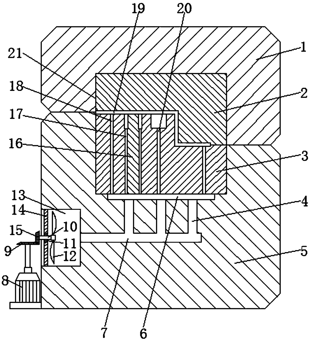
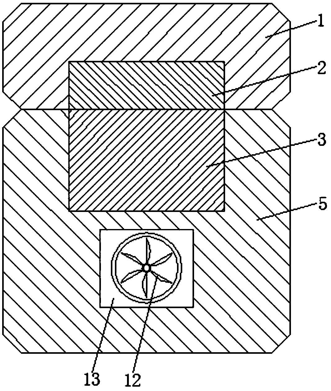
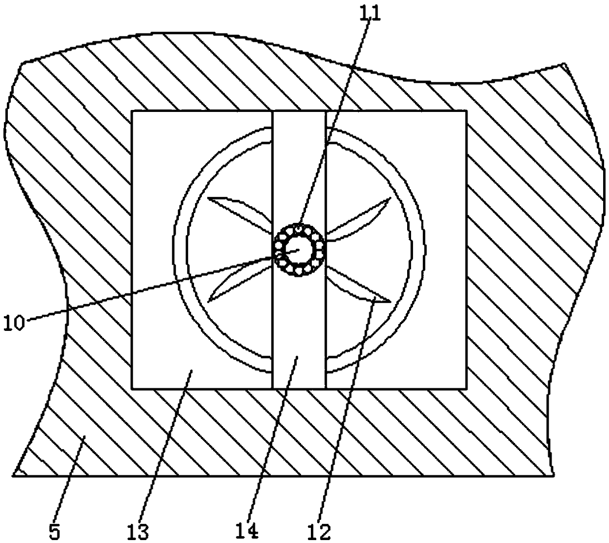
[0016] refer to Figure 1-3 , an exhaust auxiliary device for a plastic mold, comprising a movable template 1 and a fixed template 5, a movable mold cavity 2 is arranged at the lower middle position of the movable template 1, a fixed mold cavity 3 is arranged at the upper middle position of the fixed template 5, and the fixed mold A core 21 is arranged between the cavity 3 and the movable model cavity 2, a core exhaust hole 20 is arranged in the middle of the core 21, a movable mold exhaust groove 19 is arranged at the lower end of the movable model cavity 2, and a fixed mold cavity 3 is provided with A plurality of exhaust inserts 16, passages 17 are arranged betwee...


PUM


Abstract

The invention relates to the technical field of plastic moulds, in particular to an exhaust auxiliary device for a plastic mould. The exhaust auxiliary device comprises a moving die plate and a fixeddie plate, wherein the middle of the lower portion in the moving die plate is provided with a moving die mold cavity, the middle of the upper portion in the fixed die plate is provided with a fixed die mold cavity, a mold core is arranged between the fixed die mold cavity and the moving die mold cavity, the middle in the mold core is provided with a mold core exhaust hole, the lower end of the moving die mold cavity is provided with a moving die exhaust groove, the fixed die mold cavity is internally provided with multiple exhaust inserts, channels are formed among the exhaust inserts, the lower end of the fixed die mold cavity is provided with a fixed die exhaust groove, the fixed die plate is internally provided with multiple secondary exhaust holes, the secondary exhaust holes are all communicated with the fixed die exhaust groove, the fixed die plate is internally provided with a main exhaust hole, the lower portion of one side of the fixed die plate is provided with a mounting through hole, the mounting through hole is communicated with the main exhaust hole, and the mounting through hole is internally provided with an exhaust auxiliary mechanism. The exhaust auxiliary devicefor the plastic mould has the advantages that the exhaust effect is good, the exhaust efficiency is high, and the practicability is high.

Description

technical field [0001] The invention relates to the technical field of plastic molds, in particular to an exhaust auxiliary device for plastic molds. Background technique [0002] The speed at which the injection molding machine injects plastic into the mold cavity even exceeds the speed of bullet injection. The speed is unimaginable. The injection molding machine injects plastic into the mold cavity through the nozzle with several tons of pressure. The air in the cavity must be The faster the discharge speed, the plastic can fill the mold cavity. The mold cavity is open, and the mold parting surface is tightly closed by the mold. If the gas is discharged from a very small gap, the exhaust efficiency will be low, causing the pressure of the mold cavity to rise sharply, and the parts in the mold cavity will They must be subjected to super-strong pressure, and the plastic is also solidified under strong pressure, which will cause very serious consequences. Therefore, the exh...

Claims


Application Information

Patent Timeline
Patent Type & Authority Applications(China)
IPC IPC(8): B29C45/34
CPCB29C45/34
Inventor 陈胜王建曹礼连林华兵李涛
Owner HUANGSHI DINGSHENG MOLD CO LTD
Why Eureka
Try Eureka