Integrated pipe pile

A technology of integrated pipe and pile body, which is applied in the direction of sheet pile wall, building, foundation structure engineering, etc. It can solve problems such as bending, deformation, and large force on the lower end, and achieve the effect of reasonable structure, enhanced strength, and easy extrusion of soil

Inactive Publication Date: 2019-01-25
开平市建和管桩有限公司
View PDF0 Cites 1 Cited by
  • Summary
  • Abstract
  • Description
  • Claims
  • Application Information

AI Technical Summary

Problems solved by technology

When the pipe pile is used, when it is driven into the ground, the lower end is under a large force, which is easy to cause deformation, bending and other problems

Method used


Image

  • Integrated pipe pile
  • Integrated pipe pile

Examples


Embodiment Construction

[0015] The best embodiment of the present invention will be further described in detail below.

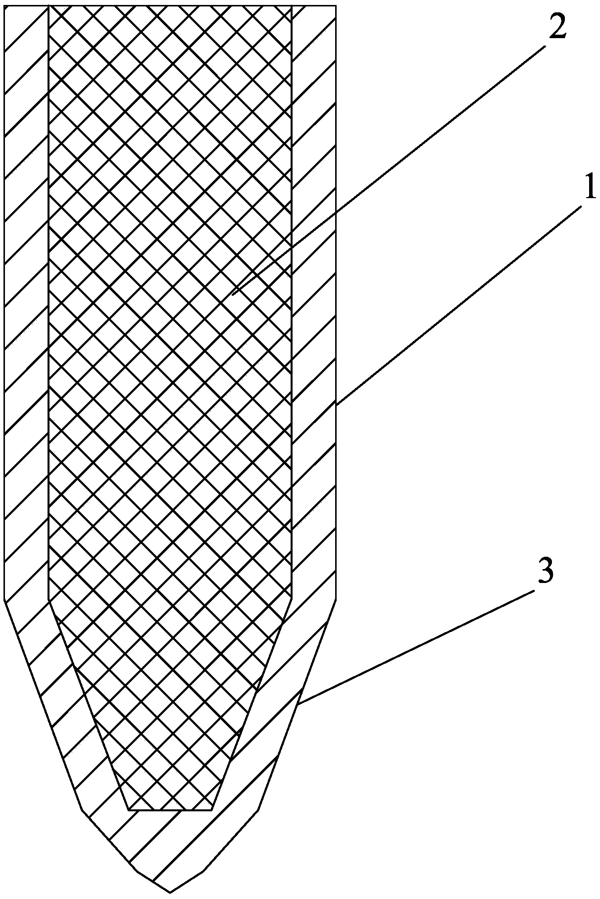
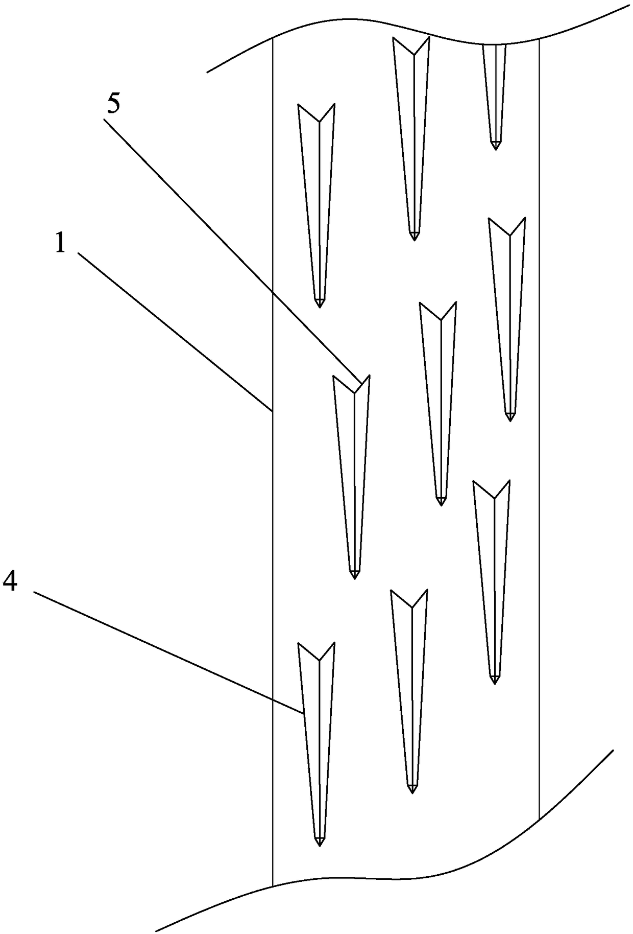
[0016] Such as Figure 1-2 As shown, in the embodiment of the present invention, the integrated pipe pile includes a pile body 1, a pile head 2, poured cement 3, and a convex edge 4. The pile body 1 is a hollow tubular structure, and the lower end of the pile body 1 is provided with an integrated structure. The pile cap 2, the pile cap 2 is a closed conical structure extending downward; the pile body 1 is provided with pouring cement 3, and the outer wall of the pile body 1 is provided with evenly distributed ribs 4, which are convenient Squeeze the soil to facilitate driving into the ground, and pouring cement 3 increases the strength of the pipe pile.

[0017] The rib 4 is a structure arranged along the axial direction of the pile body 1 .

[0018] The height of the ribs 4 gradually increases from bottom to top.

[0019] The width of the rib 4 gradually increases from bottom t...


PUM


Abstract

The invention discloses an integrated pipe pile which comprises a pile body, a pile head, pouring cement and ribs. The pile body is of a hollow tubular structure, a pile cap with an integral structureis arranged at the lower end of the pile body, and the pile cap is of an enclosed conical structure extending downward; the pile body is provided with the pouring cement, and the outer wall of the pile body is provided with the uniformly distributed ribs. The lower end of the pile body is more reasonable in structure, prone to squeeze out the soil and not easy to deform. The strength of the pipepile is improved, the market demand is met, and the pipe pile is favorable for product promotion.

Description

technical field [0001] The invention belongs to the technical field of construction, and in particular relates to an integrated pipe pile. Background technique [0002] Common steel piles are mainly pipe piles or H-shaped steel. When the pipe pile is used, when it is driven into the ground, its lower end is subjected to a large force, which is likely to cause problems such as deformation and bending. Contents of the invention [0003] The purpose of the present invention is to propose an integrated pipe pile, which overcomes the above-mentioned deficiencies in the prior art. The structure of the lower end of the pile body is more reasonable, it is easy to squeeze out the soil, and it is not easy to deform. The structural design of pouring cement enhances the strength of the pipe pile. , which meets the needs of the market and is conducive to product promotion. [0004] In order to achieve the above-mentioned design purpose, the technical scheme adopted in the present inv...

Claims


Application Information

Patent Timeline
Patent Type & Authority Applications(China)
IPC IPC(8): E02D5/24E02D5/28
CPCE02D5/24E02D5/285
Inventor 孟德江赵庆祥谭丽花
Owner 开平市建和管桩有限公司
Why Eureka
Try Eureka