[0021] Examples:
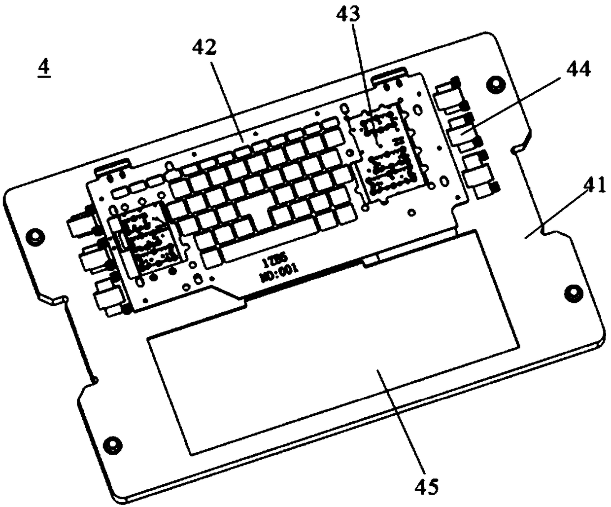
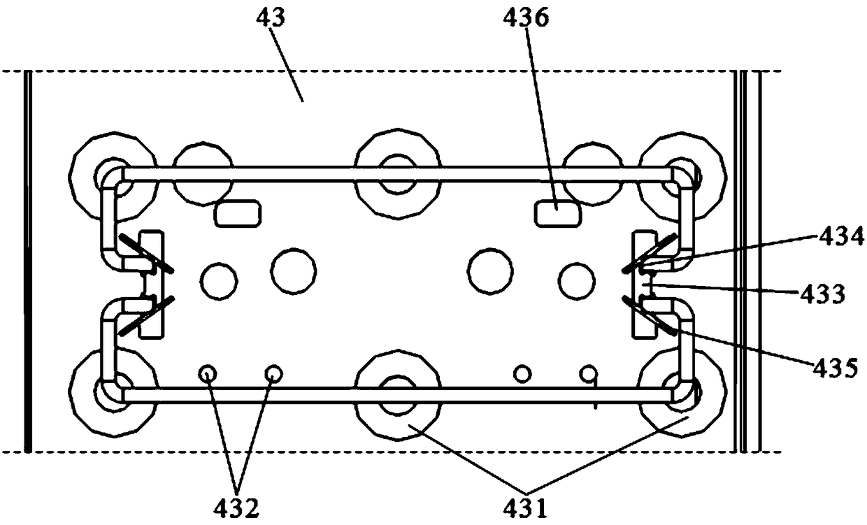
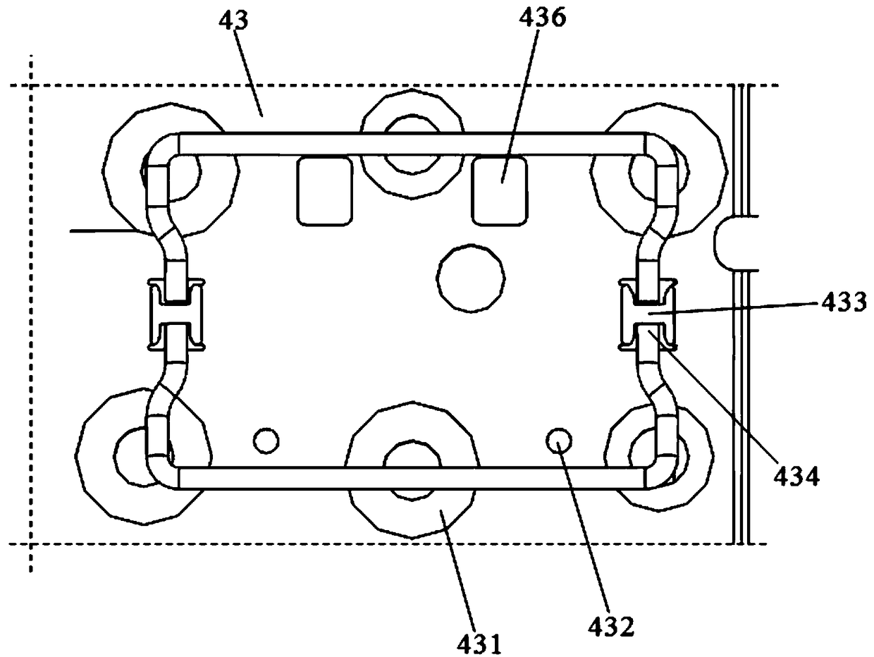
[0022] Please refer to Figure 1-Figure 3 This embodiment is a tooling structure 4 for keyboard assembly, which includes a supporting bottom plate 41 and a pressing plate 42 for flattening the substrate. The supporting bottom plate 41 is provided with a substrate receiving groove 43. The substrate receiving groove 43 is provided with an installation auxiliary mechanism for limiting the installation of the balance bar and the keycap of the special function key. The installation auxiliary mechanism includes a second installation that is embedded on the supporting bottom plate 41 and sucks the balance bar downwards. A magnetic block 431, an elastic thimble 432 that lifts the shaft support in the base plate upward, a limiting block 433 that limits the end of the balance bar, and a pressure support block 436 that supports the shaft support.
[0023] The limit block 433 is provided with a limit groove 434 that limits the depth of the end of the balance rod inserted into the substrate mounting buckle.
[0024] The first magnetic block 431 is arranged along the balance bar, which can ensure that the balance bar is tightly maintained in a horizontal state after being assembled, and facilitates the smooth pressing of the key cap.
[0025] When the balance bar is installed in the base plate, there are generally two structural forms. One is the inward buckling hooks at the left and right ends. The installation of the balance bar of this structure requires the hooks on both sides to be opened from the left and right directions. They are inserted into the board mounting buckle separately; the other is without hooks on the left and right sides. The balance bar of this structure is installed directly into the board mounting buckle from the front and back direction, but when inserting, the tilt angle of the balance bar is closer to the board The surface is easier to install.
[0026] Therefore, in one embodiment, the limit groove 434 in the limit block 433 defines the degree of inward buckling of the hooks at both ends of the balance bar, and two middle limit grooves 434 are provided on the limit block 433. , Respectively limit the same end of the two balance bars. For the limit of the balance bar with hooks, an elastic baffle 435 that limits the position of the structural balance bar in the front and rear direction is also provided beside the limit stop 433. The elastic baffle 435 forms one side wall of the limiting groove 434 and is arranged at an angle with the blocking surface of the limiting groove 434, and restricts the end of the balance bar in the limiting groove 434.
[0027] In another embodiment, the limiting groove 434 in the limiting block 433 defines the position of the balance bar in the front and rear direction after the two ends of the balance bar are inserted.
[0028] In one embodiment, a keycap receiving groove 44 is provided on the supporting bottom plate 41. When the keycap is assembled, the special function keycap can be first grabbed into the keyboard assembly tooling structure 4, and then the special function keycap can be assembled by the keycap clamping mechanism.
[0029] In another embodiment, the supporting bottom plate 41 is also provided with a keycap jig receiving groove 45 next to the substrate receiving groove 43. Since the keycap needs to be painted before assembly, the keycap will be placed in the painting process. One spray paint fixture is uniformly painted. By setting the keycap fixture carrying groove 45, the painted keycap fixture can be placed in the keycap fixture carrying groove 45 with a complete set of keycaps. The key cap clamping mechanism realizes the suction and assembly of the key cap. In the previous embodiment, by first grabbing the special function keycaps into the bearing bottom plate 41, a manipulator clamping mechanism needs to be set at the front end of the assembly line, and a separate delivery device for the spraying jig keycap plate is designed to improve Cost, and increase the process. In this embodiment, it is only necessary to widen the load-bearing bottom plate 41 to directly put the painted keycap jig into it, eliminating the need for manipulator gripping structure and painting jig conveying device, reducing costs, reducing processes, and improving production effectiveness.
[0030] One side of the pressure plate 42 is hingedly arranged on the supporting bottom plate 41, a number of metal blocks (not shown in the figure) that can be adsorbed by magnets are provided on the lower surface of the periphery of the pressure plate 42, and a number of second parts corresponding to the metal blocks are provided on the supporting bottom plate 41. The two magnetic blocks (not marked in the figure) enable the pressing plate 42 to be firmly pressed on the surface of the substrate to ensure that the substrate remains flat and tightly attached to the substrate receiving groove 43.
[0031] In another embodiment, other leveling mechanisms can also be used to ensure the flatness of the substrate on the supporting bottom plate 41. For example, a number of suction holes are provided on the supporting bottom plate 41. If a leveling mechanism is added separately to form a smoothness Pinggong Station.
[0032] When the keycap is pressed in, the shaft bracket is pushed up, and the shaft bracket is made of plastic material with a certain shape. In order to ensure that the keycap is pressed down, the two sides of the shaft bracket can be smoothly locked into the keycap. In this embodiment, the pressure support block 436 is designed to support the bottom of the shaft bracket, to provide support for the shaft bracket, and to ensure that both sides of the shaft bracket are effectively and accurately locked into the keycap.
[0033] The pressure plate 42 is also provided with a number of avoidance openings (not marked in the figure) for avoiding the installation of keycaps.
[0034] The beneficial effect of the tooling structure 100 for keyboard assembly of this embodiment is that it can accurately limit the end of the balance bar and ensure that the keycap can be installed smoothly. specific,
[0035] 1) By setting the magnetic block along the track of the balance bar, the balance bar is adsorbed by the magnetic block and tightly attached to the surface of the substrate after the balance bar is installed, maintaining a horizontal immobile state;
[0036] 2) By setting a limit block to limit the end of the balance bar, prevent the balance bar from being inserted too deep or too shallow, or too left or too right, so that the balance bar can be kept within the set range and the keycap Smoothly pressed in;
[0037] 3) By setting the elastic baffle, the space of the limit groove in the limit block can be adjusted, and the elastic function of the elastic baffle is used to limit the balance bar in the limit groove and cannot move back and forth, improving Improved the positional stability and accuracy of the balance bar;
[0038] 4) By setting the elastic thimble, it can ensure that when the keycap of the special function button is installed, the pivot bracket at the place is in the raised state, so as to ensure the smooth and damage-free assembly of the keycap, and improve product quality and product yield;
[0039] 5) This solution also supports the bottom of the shaft bracket by setting a pressure support block to provide supporting force for the shaft bracket to ensure that both sides of the shaft bracket are effectively and accurately locked into the keycap.