Rotatable magnetic glass wiper

A glass wiping and rotating magnet technology, applied in cleaning equipment, household appliances, applications, etc., can solve the problems of high safety hazards, laborious and low efficiency of magnetic glass wiping, and achieve reliable work, high wiping efficiency, and good cleaning effect. Effect

Inactive Publication Date: 2019-01-29
赵雅琪
View PDF0 Cites 5 Cited by
  • Summary
  • Abstract
  • Description
  • Claims
  • Application Information

AI Technical Summary

Problems solved by technology

[0003] At present, in the construction of residential buildings, in order to improve the light transmittance of the units, floor-to-ceiling glass doors and windows are often used in large areas, especially in public buildings such as large office buildings and shopping malls. The inner and outer surfaces of the glass are disturbed by external dust for a long time, and the surface will remain Some dust and impurities affect the aesthetics of the glass and are not conducive to the light transmittance of the room. Therefore, manual cleaning of the glass is often used. However, the glass on the outer surface of the building is difficult to clean. Using a hanging basket to clean the glass manually has a great potential safety hazard, wasting manpower and cost High, so in order to clean the outer surface of the glass more conveniently, a magnetic glass wiper was born. The purpose of cleaning the outer surface of the glass is to achieve the purpose of cleaning the outer surface of the glass by pushing two mutually attracted glass wipers. This method can clean the outer surface of the glass on the building. And the use safety is high, but because the glass wiper uses a permanent magnet, the friction between the two glass wipers is large, and the amount of impurities and dust on the surface of the glass often requires repeated cleaning to remove the impurities and dust on the outer layer of the glass. Using traditional magnetic force Glass cleaning is laborious and inefficient

Method used


Image

  • Rotatable magnetic glass wiper
  • Rotatable magnetic glass wiper
  • Rotatable magnetic glass wiper

Examples


Embodiment

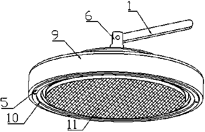
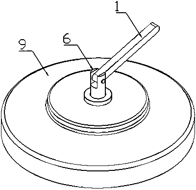
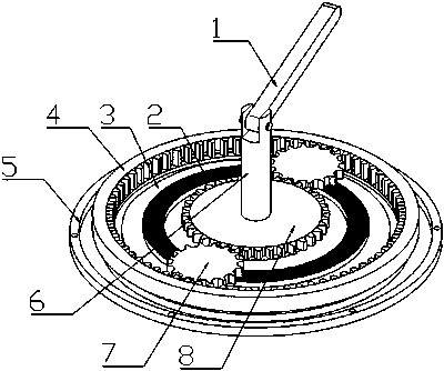
[0026] as attached Figures 1 to 6 shown

[0027] The invention provides a rotatable magnetic glass wiper, which includes a handle 1, a rotating magnet 2, a fixed disk 3, an inner gear ring 4, a fixed magnet 5, a rotating shaft 6, a planetary gear 7, a sun gear 8, a casing 9, and a slot 10 , wiping cloth 11 and bearing 12; the lower end of the casing 9 is provided with an annular draw-in groove 10, and the ring-shaped fixed magnet 5 is fixedly connected to the bottom surface of the draw-in groove 10 through screws, and the lower end surface of the fixed magnet 5 extends out of the draw-in groove 10. The rotating shaft 6 is installed on the upper end of the casing 9 through the bearing 12, the rotating shaft 6 protruding from the upper end of the casing 9 is hinged with a handle 1, and a sun gear 8 is fixedly connected to the rotating shaft 6 extending into the inside of the casing 9, and the lower end of the sun gear 8 is fixed A fixed disc 3 is connected, and an inner ring g...


PUM


Abstract

The invention provides a rotatable magnetic glass wiper. An annular clamping groove is arranged at the lower end of a shell, an annular fixed magnet is fixedly connected to the bottom surface of the clamping groove through a screw, the lower end face of the fixed magnet extends out of the clamping groove, a rotation shaft is mounted at the upper end of the shell through a bearing, the part, extending out of the upper end of the shell, of the rotation shaft is hinged to a handle, a sun gear is fixedly connected to the part, extending into the shell, of the rotation shaft, a fixing plate is fixedly connected to the lower end of the sun gear, an inner gear ring is fixedly connected to the lower end of the shell, each of two sides of the sun gear is meshed with a planetary gear, and the two planetary gears are fixedly connected to the fixing plate through rotation shafts. For the rotatable magnetic glass wiper, the inner and outer surfaces of glass are cleaned by adopting the combinationmanner using a rotating magnet and the fixed magnet, the rotating magnet rotates for driving a wiping rag to rotate, then the inner and outer surfaces of the glass are wiped, meanwhile, during the wiping process, the rotatable magnetic glass wiper can move all around, so that the wiping efficiency is high, and the cleaning effect is good.

Description

technical field [0001] The invention belongs to the technical field of glass wipes, in particular to a rotatable magnetic glass wipe. Background technique [0002] Glass usually refers to silicate glass, made of quartz sand, soda ash, feldspar and limestone as raw materials, after mixing, high-temperature melting, homogenization, processing and forming, and then annealing. Widely used in construction, daily use, art, medical treatment, chemistry, electronics, instrumentation, nuclear engineering and other fields. [0003] At present, in the construction of residential buildings, in order to improve the light transmittance of the units, floor-to-ceiling glass doors and windows are often used in large areas, especially in public buildings such as large office buildings and shopping malls. The inner and outer surfaces of the glass are disturbed by external dust for a long time, and the surface will remain Some dust and impurities affect the aesthetics of the glass and are not ...

Claims


Application Information

Patent Timeline
Patent Type & Authority Applications(China)
IPC IPC(8): A47L1/12
CPCA47L1/12
Inventor 赵雅琪
Owner 赵雅琪
Why Eureka
Try Eureka