
Spherical crown shaped embedded ultrasonic transducer

An ultrasonic transducer and embedded technology, applied in chemical instruments and methods, cleaning methods and utensils, cleaning methods using liquids, etc., can solve the problem of large space occupation in the height dimension, weak ability to apply electric power, and not small and beautiful appearance and other problems, to achieve the effect of beautiful appearance, high electric power, and improvement of the ability to apply electric power

Inactive Publication Date: 2019-01-29
杭州瑞利超声科技有限公司
View PDF7 Cites 4 Cited by
  • Summary
  • Abstract
  • Description
  • Claims
  • Application Information

AI Technical Summary

Problems solved by technology

However, it has the disadvantage of low power. Generally, it is necessary to form a planar array with multiple vibrators to improve the overall power characteristics.
Due to the rigid connection between the vibrator and the watertight support shell, there are disadvantages such as large volume and high noise
[0003] In order to solve the shortcomings of the transducer’s weak ability to apply electric power, transducer experts at home and abroad have invented such as push-pull transducers by increasing the number of ceramic sheets, increasing the length of the tool head, and increasing the contact area with water. Wait, but these transducers need to be installed from top to bottom, which has obvious disadvantages such as loud noise and large space occupation in the height dimension, which is not conducive to home use
[0004] Whether it is an ultrasonic vibrating box composed of multiple vibrators, or an ultrasonic wand with a push-pull tool head, for household applications, there are significant shortcomings such as high noise, large volume, and not compact and beautiful appearance.

Method used


Image

  • Spherical crown shaped embedded ultrasonic transducer

Examples


Embodiment Construction

[0015] The present invention will be described in detail below in conjunction with accompanying drawing:

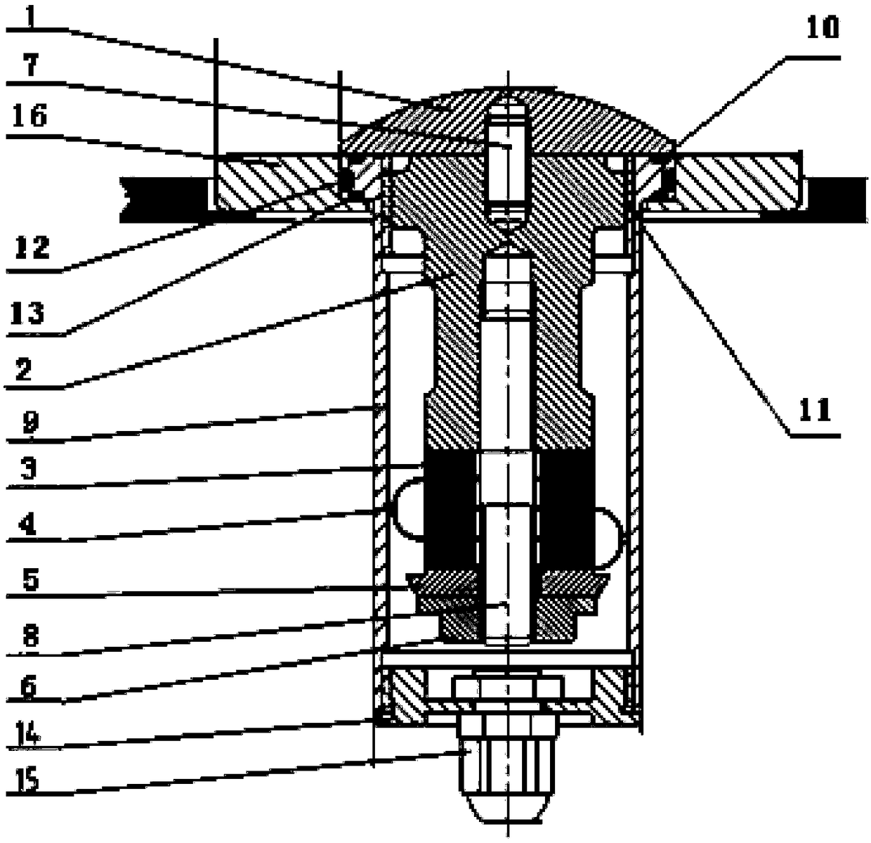
[0016] Embodiment: As shown in the accompanying drawings, this spherical crown type embedded ultrasonic transducer mainly includes a spherical crown type radiation head 1, a cylindrical horn 2, a piezoelectric ceramic sheet 3, an electrode sheet 4, a rear cover 5, Back cover nut 6, screw rod A7, screw rod B8, transfer sealing shell 9, sealing ring A10, sealing ring B11, sealing ring C12, sealing ring D13, sealing end cover 14, watertight plug 15, sink bottom 16, spherical crown type The radiation head 1 and the cylindrical horn 2 are mechanically connected in series through the screw rod A7 to form the tool head, and the tool head, the piezoelectric ceramic stack 3, the electrode piece 4, the back cover 5, and the back cover nut 6 are mechanically connected in series through the screw rod B8 to form the tool head. The whole transducer is placed in the transfer seal housin...


PUM


Abstract

The invention discloses a spherical crown shaped embedded ultrasonic transducer. The spherical crown shaped embedded ultrasonic transducer mainly comprises a spherical crown shaped radiation head, etc., wherein the spherical crown shaped radiation head and a cylindrical amplitude-change pole are mechanically connected in series to form a tool head through a screw A; the tool head is chemically connected in series with a piezoelectric ceramic reactor, an electrode plate, a rear cover and a rear cover to form a transducer body through screws B; the transducer body is arranged to an adapting sealing housing; a sealing end cover which is connected to a water seal plug is connected to the bottom part of the adapting sealing housing; the adapting sealing housing is arranged at the bottom part ofa water tank and is flexibly connected to the water tank through a sealing ring C and a sealing ring D; and the spherical crown shaped radiation head is in contact with water in the water tank and iscapable of radiating acoustical energy. According to the spherical crown shaped embedded ultrasonic transducer, the electric power applying capacity of the transducer is improved; the noise producedby radiation of the transducer through the water tank is extremely reduced; the design requirements of cavitation corrosion resistance of the tool head and low overall manufacturing cost can be met; and the spherical crown shaped embedded ultrasonic transducer is a spherical crown shaped radiating surface type embedded ultrasonic transducer which is small in size, nice in appearance, and wide in applicable scope.

Description

technical field [0001] The invention relates to the field of ultrasonic transducer technology, in particular to a spherical crown embedded ultrasonic transducer. Background technique [0002] Ultrasonic cleaning transducers widely used at present have remarkable features such as simple structure, low cost, stable and reliable performance, etc. However, it has the disadvantage of low power. Generally, it is necessary to form a planar array with multiple vibrators to improve the overall power characteristics. Due to the rigid connection between the vibrator and the watertight supporting shell, there are disadvantages such as large volume and high noise. [0003] In order to solve the shortcomings of the transducer’s weak ability to apply electric power, transducer experts at home and abroad have invented such as push-pull transducers by increasing the number of ceramic sheets, increasing the length of the tool head, and increasing the contact area with water. Wait, but these...

Claims


Application Information

Patent Timeline
IPC IPC(8): B08B3/12B06B1/06
CPCB06B1/06B08B3/12
Inventor 刘文静刘细宝金杭超
Owner 杭州瑞利超声科技有限公司
Learn More