Automatic corrugated pipe cleaning device

A technology for cleaning devices and bellows, which is applied to heating devices, cleaning hollow objects, cleaning methods and utensils, etc., can solve problems such as inability to clean and dry effects, and achieve cleaning and drying effects. The effect of drying

Inactive Publication Date: 2019-01-29
SUZHOU GUIGUO ELECTRONICS
View PDF1 Cites 2 Cited by
  • Summary
  • Abstract
  • Description
  • Claims
  • Application Information

AI Technical Summary

Problems solved by technology

In the above solution, the spaces for cleaning and drying overlap each other, and multiple bellows are stacked in the box, which makes it impossible to thoroughly clean the inside of the bellows, and at the same time, the drying effect will also be affected

Method used


Image

  • Automatic corrugated pipe cleaning device
  • Automatic corrugated pipe cleaning device
  • Automatic corrugated pipe cleaning device

Examples


Embodiment 1

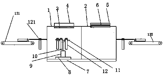
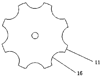
[0026] An automatic cleaning device for bellows, comprising a connected cleaning room and a drying room, the top of the cleaning room is provided with a spray head, the cleaning room and the drying room are separated by a pvc curtain, the spray head is connected to the water tank, and the water tank Filled with cleaning liquid; the top of the drying chamber is provided with an air outlet of the air duct, the air duct is connected to the fan, and the heating resistance wire is arranged in the air duct; the cleaning chamber and the bottom of the drying chamber are provided with two The track of the room is equipped with a slider on the track, and a motor is installed on the slider. The motor is an AKM series servo motor. The rotating rod of the motor is arranged vertically upwards. It is circular, and the end of the rotating rod is connected to the center of the hanging plate. There are multiple semicircular notches evenly distributed on the edge of the hanging plate. The opening...

Embodiment 2

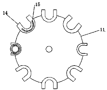
[0028] The top of the hanging plate is located at each notch and is provided with a U-shaped insert, the U-shaped insert covers the gap, the opening direction of the U-shaped insert is consistent with the opening direction of the notch, and the top of the U-shaped insert A semicircular protrusion is provided, a collar is sleeved on the end of the bellows, and an annular groove corresponding to the semicircular protrusion is provided on the contact surface of the collar and the U-shaped insert.

Embodiment 3

[0030] The bellows inlet is set on the side wall of the cleaning room, and the bellows outlet is opened on the side wall of the drying room. The bellows inlet is connected to the input conveyor belt, and the bellows outlet is connected to the output conveyor belt. Input transmission and output transmission A pair of mechanical arms (not visible in the figure) are respectively arranged on the belt. The mechanical arms are four-axis mechanical arms, which can move horizontally and vertically. There is an electromagnet at the end of the shaft; a horizontal bellows is placed on the input conveyor belt, and a collar is sleeved on the bellows. The collar is made of stainless steel. The mechanical arm above the input conveyor belt absorbs the collar through the electromagnet. Grab the corrugated pipe, and then rotate the horizontally placed corrugated pipe by 90° counterclockwise by operating the rotating shaft to vertically place it. Finally, the operating arm hooks the corrugated pi...


PUM


Abstract

The invention relates to the field of corrugated pipe machining automation, in particular to an automatic corrugated pipe cleaning device. The device comprises a cleaning chamber and a drying chamberwhich are connected, a spraying head is arranged on the top of the cleaning chamber and is connected with a water tank, the water tank is filled with cleaning liquid, an air outlet of an air flue is formed in the top of the drying chamber, the air flue is connected with a fan, a rail for penetrating through the two chambers is arranged on the bottoms of the cleaning chamber and the drying chamber,a sliding block is arranged on the rail, a motor is arranged on the sliding block, a rotation rod of the motor is vertically and upwards arranged, a hanging disc is arranged at the end of the rotation rod, and is round, the end of the rotation rod is connected to the circle center of the hanging disc, multiple semicircular gaps are evenly distributed in the edge of the hanging disc, the opening direction of the gaps is arranged in the radial direction of the hanging disc, and a corrugated pipe is arranged in the gaps in a hanging connection manner. Through the corrugated pipe hanging connection manner, the corrugated pipe is cleaned, and the advantages of being good in cleaning effect and convenient to dry are achieved.

Description

technical field [0001] The invention relates to the field of bellows processing automation, in particular to an automatic cleaning device for bellows. Background technique [0002] Bellows refers to a tubular elastic sensitive element connected by foldable corrugated sheets along the direction of folding and stretching. Bellows are widely used in instruments and meters, and their main purpose is as a measuring element of a pressure measuring instrument to convert pressure into displacement or force. The bellows has a thinner wall and higher sensitivity, and the measurement range is tens of Pa to tens of MPa. Its open end is fixed, and the sealed end is in a free state, and the auxiliary coil spring or reed is used to increase the elasticity. When working, under the action of internal pressure, it is elongated along the length of the pipe, so that the movable end produces a displacement that has a certain relationship with the pressure. The movable end drives the pointer t...

Claims


Application Information

Patent Timeline
IPC IPC(8): B08B9/032B08B9/023F26B21/00F26B23/06
CPCB08B9/0321B08B9/023B08B2209/032F26B21/001F26B23/06
Inventor 费芬芳
Owner SUZHOU GUIGUO ELECTRONICS
Why Eureka
Try Eureka