Brake light control method, storage medium and electronic device

A control method and technology of brake lights, which are applied to vehicle components, signal devices, optical signals, etc., can solve problems such as not being able to reflect vehicle driving intentions well, reduce insufficient braking, improve driving safety, reduce braking wasteful effect

Active Publication Date: 2022-03-15
SAIC GENERAL MOTORS +1
View PDF12 Cites 0 Cited by
  • Summary
  • Abstract
  • Description
  • Claims
  • Application Information

AI Technical Summary

Problems solved by technology

At present, the brake light of the vehicle mainly has two modes of on and off. When the driver steps on the brake pedal, the brake light of the vehicle lights up and emits red light to warn the vehicles behind to prevent rear-end collision; when the driver releases the brake pedal When the pedal is moved, the vehicle brake light goes out, and the existing vehicle brake light mode cannot reflect the vehicle's driving intention well

Method used


Image

  • Brake light control method, storage medium and electronic device
  • Brake light control method, storage medium and electronic device
  • Brake light control method, storage medium and electronic device

Examples


Embodiment 1

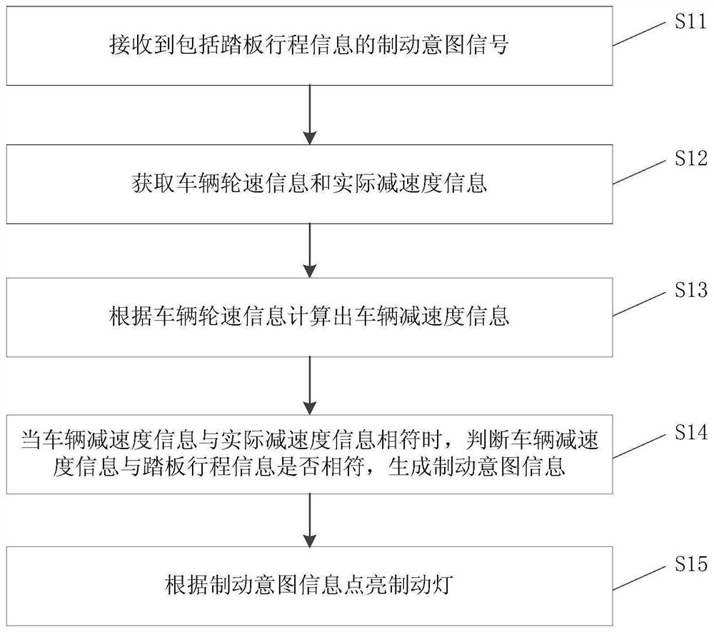
[0053] like figure 1 as shown, figure 1 It is a work flow chart of a brake light control method provided by an embodiment of the present invention, including:

[0054] Step S11: receiving a braking intention signal including pedal stroke information;

[0055] Step S12: Obtain vehicle wheel speed information and actual deceleration information;

[0056] Step S13: Calculate the vehicle deceleration information according to the vehicle wheel speed information;

[0057] Step S14: When the vehicle deceleration information is consistent with the actual deceleration information, determine whether the vehicle deceleration information is consistent with the pedal stroke information, and generate braking intention information;

[0058] Step S15: turn on the brake lights according to the braking intention information.

[0059]Specifically, a vehicle running on the road can receive a braking intention signal including pedal stroke information through a device with processing capabilit...

Embodiment 2

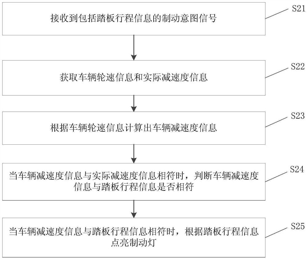
[0063] like figure 2 as shown, figure 2 It is a work flow chart of a brake light control method provided by an optional embodiment of the present invention, including:

[0064] Step S21: receiving a braking intention signal including pedal stroke information;

[0065] Step S22: Obtain vehicle wheel speed information and actual deceleration information;

[0066] Step S23: Calculate the vehicle deceleration information according to the vehicle wheel speed information;

[0067] Step S24: When the vehicle deceleration information matches the actual deceleration information, determine whether the vehicle deceleration information matches the pedal stroke information;

[0068] Step S25: When the vehicle deceleration information matches the pedal stroke information, turn on the brake light according to the pedal stroke information.

[0069] Specifically, when the vehicle deceleration information is consistent with the pedal travel information, it indicates that the braking inten...

Embodiment 3

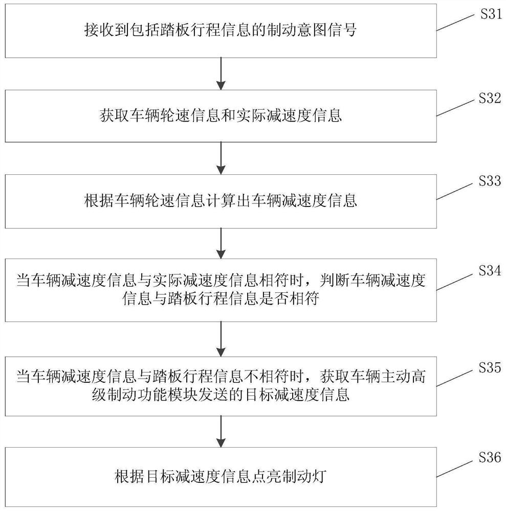
[0072] like image 3 as shown, image 3 It is a work flow chart of a brake light control method provided by another embodiment of the present invention, including:

[0073] Step S31: receiving a braking intention signal including pedal stroke information;

[0074] Step S32: Obtain vehicle wheel speed information and actual deceleration information;

[0075] Step S33: Calculate the vehicle deceleration information according to the vehicle wheel speed information;

[0076] Step S34: When the vehicle deceleration information matches the actual deceleration information, determine whether the vehicle deceleration information matches the pedal stroke information;

[0077] Step S35: when the vehicle deceleration information does not match the pedal travel information, obtain the target deceleration information sent by the active advanced braking function module of the vehicle;

[0078] Step S36: Turn on the brake light according to the target deceleration information.

[0079] S...


PUM


Abstract

The invention discloses a brake light control method, storage medium and electronic equipment. The method comprises: receiving a braking intention signal including pedal stroke information; acquiring vehicle wheel speed information and actual deceleration information; Calculate the vehicle deceleration information from the deceleration information; when the vehicle deceleration information is consistent with the actual deceleration information, judge whether the vehicle deceleration information is consistent with the pedal stroke information, and generate braking intention information; according to the The above braking intention message turns on the brake lights. By implementing the present invention, the braking intention can be judged more accurately, and the brake lights can be lighted according to the braking intention, which can better reflect the driving intention of the vehicle, make the braking force of the front and rear vehicles consistent to a certain extent, and effectively reduce the waste of braking. And insufficient braking, improve driving safety and reduce traffic jams.

Description

technical field [0001] The invention relates to the technical field of automobiles, in particular to a brake light control method, a storage medium and electronic equipment. Background technique [0002] Vehicle brake lights are generally installed on the left and right sides of the rear of the vehicle. They are used as warning lights for motor vehicles to remind vehicles behind to avoid collisions when braking, and to prevent rear-end collisions. At present, the brake light of the vehicle mainly has two modes of on and off. When the driver steps on the brake pedal, the brake light of the vehicle lights up and emits red light to warn the vehicles behind to prevent rear-end collision; when the driver releases the brake pedal When the pedal is moved, the vehicle brake light goes out, and the existing vehicle brake light mode cannot well reflect the vehicle's driving intention. Contents of the invention [0003] The object of the present invention is to provide a brake light...

Claims


Application Information

Patent Timeline
Patent Type & Authority Patents(China)
IPC IPC(8): B60Q1/44
CPCB60Q1/444
Inventor 张贤超崔海峰朱玙熹杨洪福
Owner SAIC GENERAL MOTORS
Why Eureka
Try Eureka