Accurately moving and anti-impact robot leg device

A technology of impact resistance and robotics, applied in the field of robotics, can solve the problems that the material properties cannot be fully exerted, and achieve the effects of novel transmission structure, improved impact resistance, and good buffering effect

Active Publication Date: 2019-01-29
SHANDONG UNIV OF SCI & TECH
View PDF5 Cites 1 Cited by
  • Summary
  • Abstract
  • Description
  • Claims
  • Application Information

AI Technical Summary

Problems solved by technology

However, the impact during the robot movement does not always exist. The robot with high structural strength works under a low load state most of the time, so that the material properties cannot be fully exerted.

Method used


Image

  • Accurately moving and anti-impact robot leg device
  • Accurately moving and anti-impact robot leg device
  • Accurately moving and anti-impact robot leg device

Examples


Embodiment 1

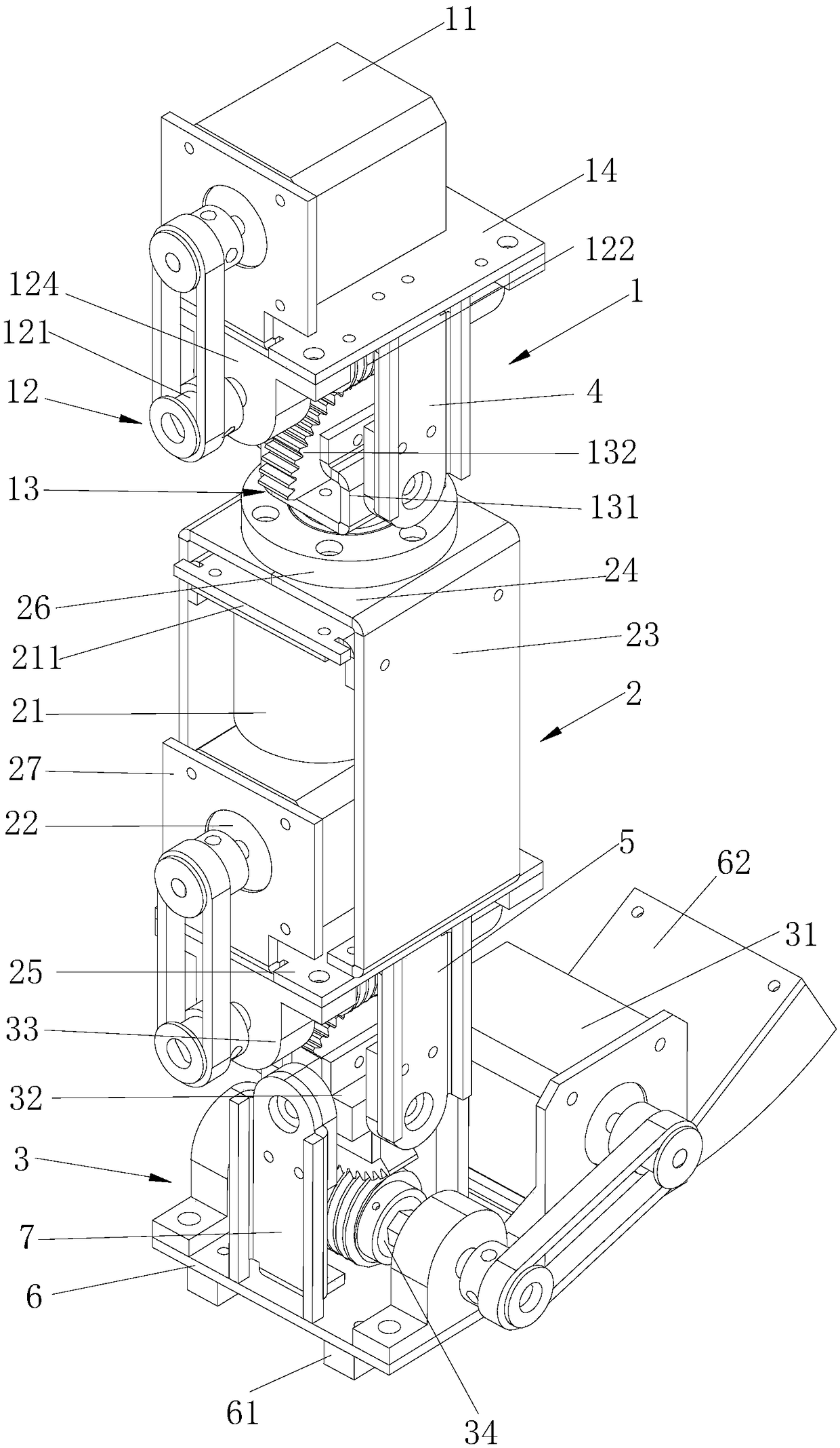
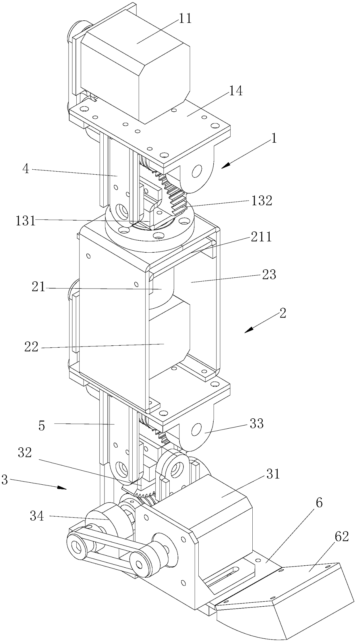
[0056] Embodiment 1. When the above-mentioned anti-impact robot leg device with precise movement is working normally, the output shaft of the first motor 11 is connected with the first worm shaft through a belt, and the first worm shaft drives the first hollow worm to rotate. The forward rotation and reverse rotation of the first motor 11 drive the forward rotation and reverse rotation of the first hollow worm 122, so that the first worm wheel 132 moves in the front and rear direction, and the first hollow worm and the first joint mechanism are connected through a worm gear transmission. . In a normal working state, the first worm gear 132 cannot drive the first hollow worm 122 to move along the axis of the first worm shaft 121 .

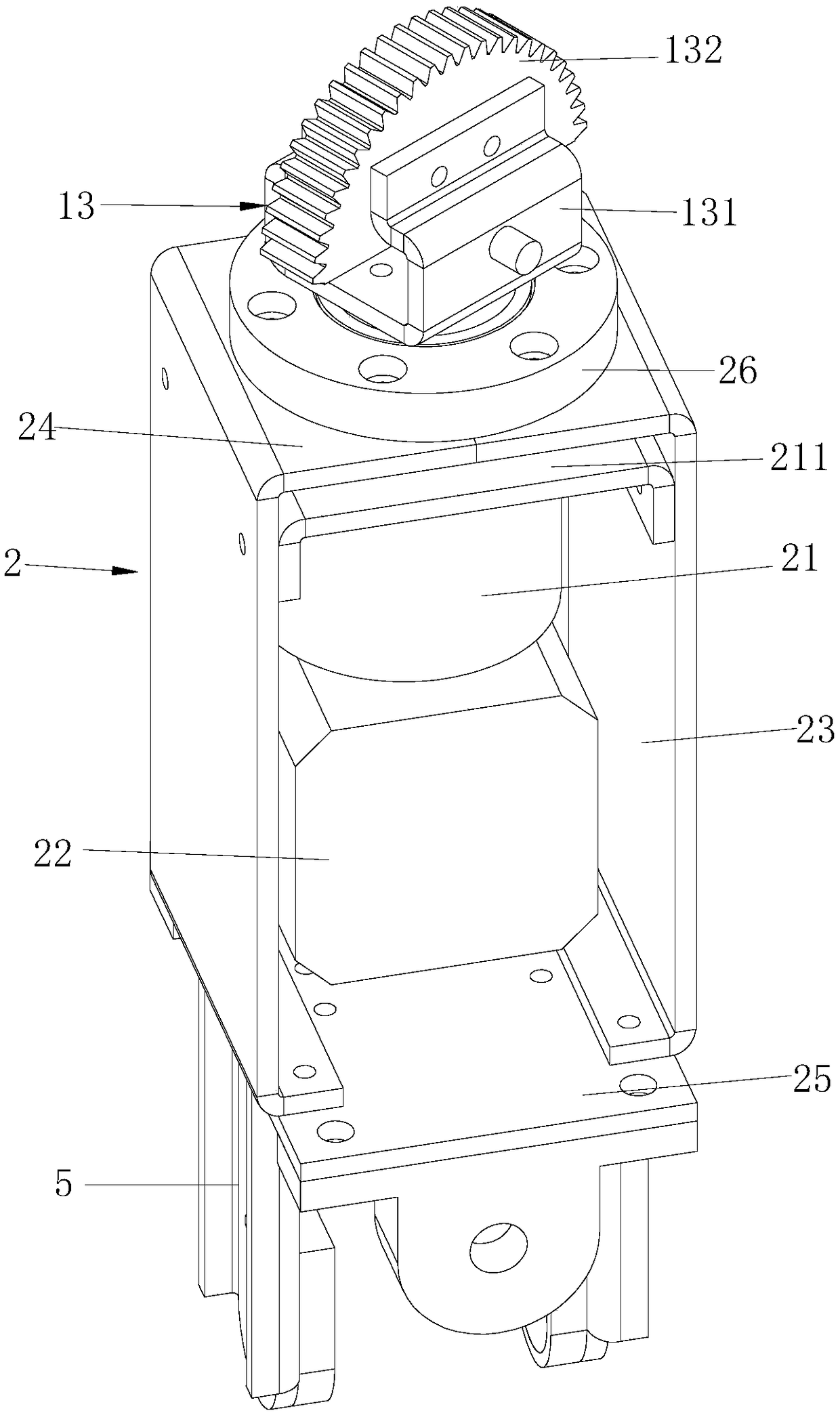
[0057] The output shaft of the second motor 21 is connected with the first joint seat 131, and the forward rotation and reverse rotation of the second motor 21 can drive the structure below the first joint mechanism 13 to rotate in the left and righ...

Embodiment 2

[0061] Embodiment 2, when the robot is impacted and the knee joint structure 1 is subjected to an impact force, and the impact force is greater than the initial pressure of the first circular spring 111 in the knee joint structure 1, the first worm gear 132 will drive the first hollow worm 122 along the second A worm shaft 121 moves in the axial direction. The force received by the knee joint structure 1 is transmitted to the first hollow worm 122 .

[0062] Due to the self-locking property of the connection between the first worm wheel 132 and the first hollow worm 122, the first worm wheel 132 cannot drive the first hollow worm 122 to rotate around the axis. The force is greater than the preload of the first circular spring 111 on the first hollow worm 122, the first hollow worm 122 will move along the axis under the pressure of the first worm wheel 132 to further compress the first circular spring 111, and the energy generated by the impact will be converted into a spring ...


PUM


Abstract

The invention discloses an accurately moving and anti-impact robot leg device. The accurately moving and anti-impact robot leg device comprises a knee joint structure, a shank structure and an ankle joint structure; the knee joint structure comprises a first motor, a first buffering transmission mechanism and a first joint mechanism; a first motor bracket is connected to the lower end of the firstmotor; the first buffering transmission mechanism comprises a first hollow worm and a first buffering spring component; the first joint mechanism comprises a first joint seat and a first worm wheel;the first worm wheel is connected to the interior of the first joint seat through a shaft pin; first connecting supports are arranged on the left and right sides of the first hollow worm; the upper ends of the first connecting supports are fixedly connected with the first motor bracket; the lower ends of the first connecting supports are rotationally connected to the first joint seat through firstsupporting shafts; the shank structure comprises a second motor, a third motor and two leg side plates; and the ankle joint structure is arranged at the lower end of the shank structure. According tothe accurately moving and anti-impact robot leg device, as the novel knee joint structure and the novel ankle joint structure are arranged, the transmission structure is simple and novel, the buffering effect is good, and the creativity is high.

Description

technical field [0001] The invention relates to the field of robots, in particular to an impact-resistant robot leg device with precise movement. Background technique [0002] The impact problem has always been an inevitable problem in the study of robot mechanical structures. Robot joints generally have many degrees of freedom. We expect the joints of the robot to move flexibly and accurately. However, when the joints accelerate or the robot collides with other objects, impacts will inevitably occur. If there is no special device to buffer the impact, The impact of a fall can damage a joint. The more common solution is to connect the buffer device in series in the transmission device. The buffer device is a flexible mechanism. Its working principle is that it will deform when it is subjected to force, and convert the instantaneous high impact force generated by the impact into a slow release of low impact force. , thereby playing a protective role. [0003] However, afte...

Claims


Application Information

Patent Timeline
Patent Type & Authority Applications(China)
IPC IPC(8): B62D57/032
CPCB62D57/032
Inventor 魏军英张聪王吉岱刘欢刘起宇
Owner SHANDONG UNIV OF SCI & TECH
Why Eureka
Try Eureka