AI technical title is built by PatSnap AI team. It summarizes the technical point description of the patent document.
A UAV and landing gear technology, applied in the field of multi-functional UAV mobile landing gear device, can solve the problems of easy cutting and wounding, fast fan blade rotation, and lack of better tools for UAV transportation and storage, which is not easy to achieve Moisture, ensure the effect of internal air circulation
Inactive Publication Date: 2019-01-29
钟夏欣
View PDF6 Cites 6 Cited by
Summary
Abstract
Description
Claims
Application Information
AI Technical Summary
This helps you quickly interpret patents by identifying the three key elements:
Problems solved by technology
Method used
Benefits of technology
Problems solved by technology
[0002] With the progress of society and the improvement of people's quality of life, more and more new tools are used. As a new tool, drones appear in people's lives and have been widely used in various industries, but no one The fan blades of the drone rotate very quickly, which is easy to cut people, and there is no better tool for the transportation and storage of the drone, so this multifunctional drone mobile landing gear device is designed.
Method used
Image
Click on the blue label to locate the original text in one second.
Reading with bidirectional positioning of images and text.
Examples
specific Embodiment approach 1
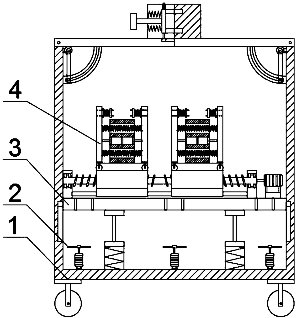
[0040] Combine below figure 1 , figure 2 , image 3 , Figure 4 , Figure 5 , Image 6 , Figure 7 , Figure 8 , Figure 9 , Figure 10 , Figure 11 , Figure 12 , Figure 13 , Figure 14 To illustrate this embodiment, the present invention relates to a landing gear device, more specifically, a multifunctional unmanned aerial vehicle mobile landing gear device, including a fuselage mechanism 1, a dehumidification fan mechanism 2, a lifting mechanism 3, and a drone clip Tightening mechanism 4, the device can move, the device can clamp the drone, the device can clamp drones of different horizontal sizes, the device can clamp drones of different longitudinal sizes, and the opening and closing door of the device can be easily locked or locked. Unlock, the device can automatically open the door, the device can ensure the internal air circulation, so that the drone is not easy to get wet.
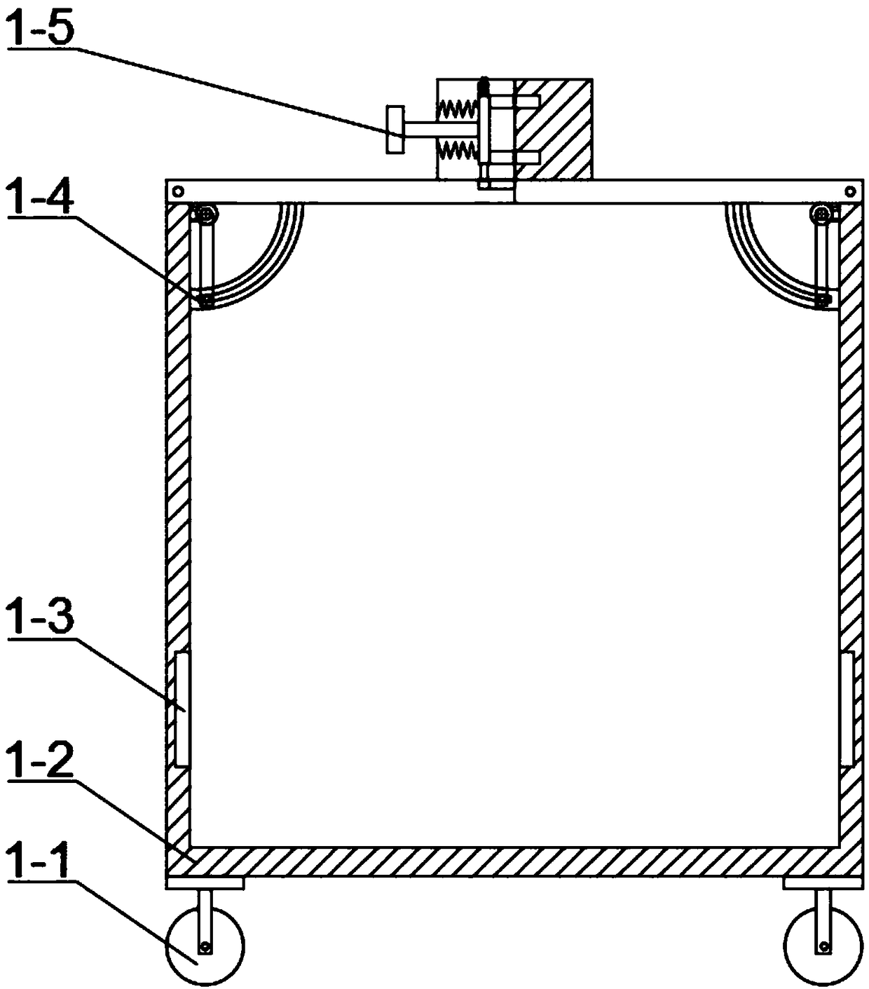
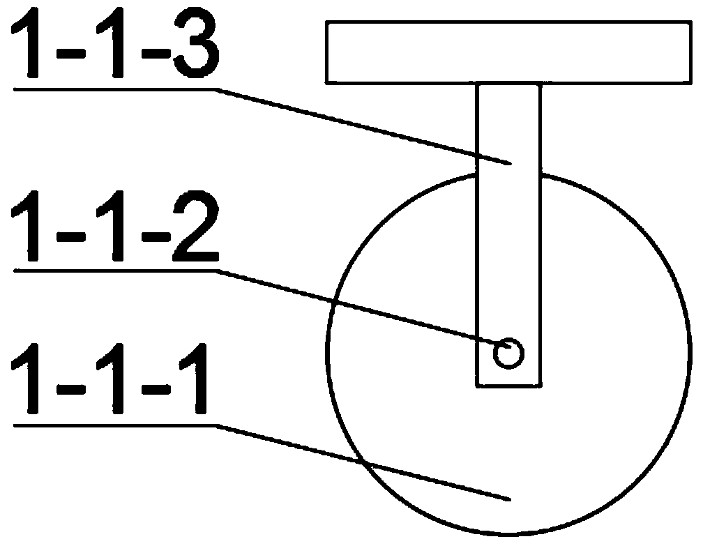
[0041] The fuselage mechanism 1 includes a moving wheel mechanism 1-1, a casing...
specific Embodiment approach 2
[0055] Combine below figure 1 , figure 2 , image 3 , Figure 4 , Figure 5 , Image 6 , Figure 7 , Figure 8 , Figure 9 , Figure 10 , Figure 11 , Figure 12 , Figure 13 , Figure 14 This embodiment will be described. This embodiment will further describe the first embodiment, and the number of the moving wheel mechanisms 1 - 1 is four.
specific Embodiment approach 3
[0056] Combine below figure 1 , figure 2 , image 3 , Figure 4 , Figure 5 , Image 6 , Figure 7 , Figure 8 , Figure 9 , Figure 10 , Figure 11 , Figure 12 , Figure 13 , Figure 14 This embodiment will be described. This embodiment will further describe Embodiment 1, and the material of the casing 1-2 is stainless steel.
PUM
Abstract
The invention relates to an undercarriage device, in particular to a multifunctional unmanned aerial vehicle moving undercarriage device. The multifunctional unmanned aerial vehicle moving undercarriage device comprises a machine body mechanism, dehumidifying fan mechanisms, a lifting mechanism and unmanned aerial vehicle clamping mechanisms. The device can be moved. The device can clamp unmannedaerial vehicles. The device can clamp unmanned aerial vehicles with different transverse sizes, the device can clamp unmanned aerial vehicles with different longitudinal sizes, a device opening and closing door can be easily locked or unlocked, and the device can automatically open the opening and closing door. The device can ensure internal air circulation, so that the unmanned aerial vehicle isnot easily affected with damp. The dehumidifying fan mechanisms are arranged in a fuselage mechanism. The connection mode of the dehumidifying fan mechanisms and the fuselage mechanism is bolt connection. The lifting mechanism is arranged in the fuselage mechanism. The connection mode of the lifting mechanism and the fuselage mechanism is partial welding and partial clearance fit. The unmanned aerial vehicle clamping mechanisms are positioned above the lifting mechanism. The connection mode of the unmanned aerial vehicle clamping mechanisms and the lifting mechanism is welding.
Description
technical field [0001] The invention relates to a landing gear device, more specifically a multifunctional unmanned aerial vehicle mobile landing gear device. Background technique [0002] With the progress of society and the improvement of people's quality of life, more and more new tools are used. As a new tool, drones appear in people's lives and have been widely used in various industries, but no one The fan blades of the drone rotate very quickly, which is easy to cut people, and there is no better tool for the transportation and storage of the drone, so this multifunctional drone mobile landing gear device is designed. Contents of the invention [0003] The technical problem mainly solved by the present invention is to provide a multifunctional unmanned aerial vehicle mobile landing gear device, the device can move, the device can clamp the unmanned aerial vehicle, the device can clamp the unmanned aerial vehicle of different lateral dimensions, and the device can cl...
Claims
Application Information
Patent Timeline
Application Date:The date an application was filed.
Publication Date:The date a patent or application was officially published.
First Publication Date:The earliest publication date of a patent with the same application number.
Issue Date:Publication date of the patent grant document.
PCT Entry Date:The Entry date of PCT National Phase.
Estimated Expiry Date:The statutory expiry date of a patent right according to the Patent Law, and it is the longest term of protection that the patent right can achieve without the termination of the patent right due to other reasons(Term extension factor has been taken into account ).
Invalid Date:Actual expiry date is based on effective date or publication date of legal transaction data of invalid patent.

