Silo bottom discharger with multi-direction vibration
A technology of unloader and longitudinal vibration, which is applied in the field of multi-directional vibration unloader at the bottom of the warehouse, which can solve the problems of arch breaking of materials in the unloading hopper, and achieve the effect of increasing unloading capacity, improving unloading capacity, and convenient control
- Summary
- Abstract
- Description
- Claims
- Application Information
AI Technical Summary
Problems solved by technology
Method used
Image

Examples
Embodiment 1
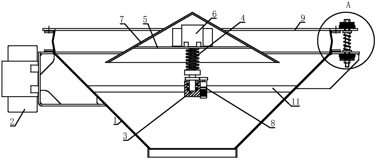
[0027] A multi-directional vibration bin bottom unloader, comprising a discharge hopper 1; a transverse vibration motor 2 is installed on the outer wall of the discharge hopper 1, a connecting frame 11 is fixed inside the discharging hopper 1, and a rotating mechanism 3 is fixed on the connecting frame , the other end of the rotating mechanism 3 is fixed with a connecting mechanism 4, the other end of the connecting mechanism 4 is fixed with a fixed plate 5, a longitudinal vibration motor 6 and a discharge tray 7 are installed on the fixed plate 5, and the longitudinal vibration motor 6 is arranged on the discharge tray 7, the shape of the discharge tray 7 is conical.
[0028] The horizontal vibration motor 2 of the present invention can apply horizontal vibration to the discharge hopper 1, and the longitudinal vibration motor 6 can apply vertical vibration to the discharge tray 7, so that the material in the discharge hopper 1 can receive horizontal and vertical vibrations. V...
Embodiment 2
[0030] On the basis of the first embodiment, the rotation direction of the polarization block of the horizontal vibration motor 2 is horizontal, and the rotation direction of the polarization block of the longitudinal vibration motor 6 is vertical.
[0031] The direction of rotation of the polarization block of the transverse vibration motor 2 is horizontal, so the transverse vibration motor 2 can apply vibration in the horizontal direction to improve the discharge capacity of the discharge hopper 1 . The direction of rotation of the polarizing block of the longitudinal vibration motor 6 is vertical, then the longitudinal vibration motor 6 can apply vertical vibration to the discharge tray 7, so as to avoid material accumulation in the area between the discharge hopper 1 and the discharge tray.
Embodiment 3
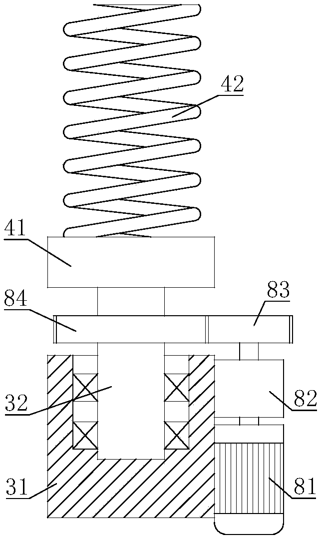
[0033] On the basis of Embodiment 1 or Embodiment 2, the rotating mechanism 3 includes a fixed groove 31, the fixed groove 31 is fixed on the connecting frame 11, the rotating shaft 32 is connected to the fixed groove 31 through a bearing, and the fixed groove 31 is installed with a useful The driving mechanism 8 is used to drive the rotating shaft 32 to rotate. The output end of the driving mechanism 8 is connected to the rotating shaft 32 , and the other end of the rotating shaft 32 is connected to the connecting mechanism 4 .
[0034] The driving mechanism 8 can drive the rotating shaft 32 to rotate, and then the rotating shaft 32 can drive the connecting mechanism 4 and the discharge tray 7 to rotate. When the discharge tray 7 rotates, the material accumulated on the discharge tray 7 can be thrown out, and the rotating discharge tray 7 can break the arch of the material, which further improves the discharge capacity of the present invention.
PUM
 Abstract
Description
Claims
Application Information
 - Generate Ideas
- Intellectual Property
- Life Sciences
- Materials
- Tech Scout
- Unparalleled Data Quality
- Higher Quality Content
- 60% Fewer Hallucinations
Browse by: Latest US Patents, China's latest patents, Technical Efficacy Thesaurus, Application Domain, Technology Topic, Popular Technical Reports.
© 2025 PatSnap. All rights reserved.Legal|Privacy policy|Modern Slavery Act Transparency Statement|Sitemap|About US| Contact US: help@patsnap.com