Beam-column joint for fabricated concrete frame structure

A frame structure, beam-column joint technology, applied in the direction of building structure, construction, etc., can solve the problems of unable to meet the performance requirements of joint connection stably, difficult to achieve precise construction, and slow down the construction progress, etc., to achieve simple and feasible design, The effect of reliable design and simplified connection form

Pending Publication Date: 2019-01-29
SOUTH CHINA UNIV OF TECH
View PDF0 Cites 6 Cited by
  • Summary
  • Abstract
  • Description
  • Claims
  • Application Information

AI Technical Summary

Problems solved by technology

However, there are also some disadvantages. For example, during the construction process, it is necessary to wait for the pouring of concrete for maintenance, which slows down the construction progress; the process of pouring concrete requires the cooperation of multiple workers, which consumes a lot of manpower; It is difficult to achieve precise construction; the construction process of cast-in-place concrete is also likely to cause pollution to the surrounding environment
However, the connection between different components of prefabricated buildings at this stage is relatively weak, and neither the dry bolted connection nor the wet cast-in-place concrete connection can stably meet the performance requirements of the node connection.

Method used


Image

  • Beam-column joint for fabricated concrete frame structure
  • Beam-column joint for fabricated concrete frame structure
  • Beam-column joint for fabricated concrete frame structure

Examples


Embodiment

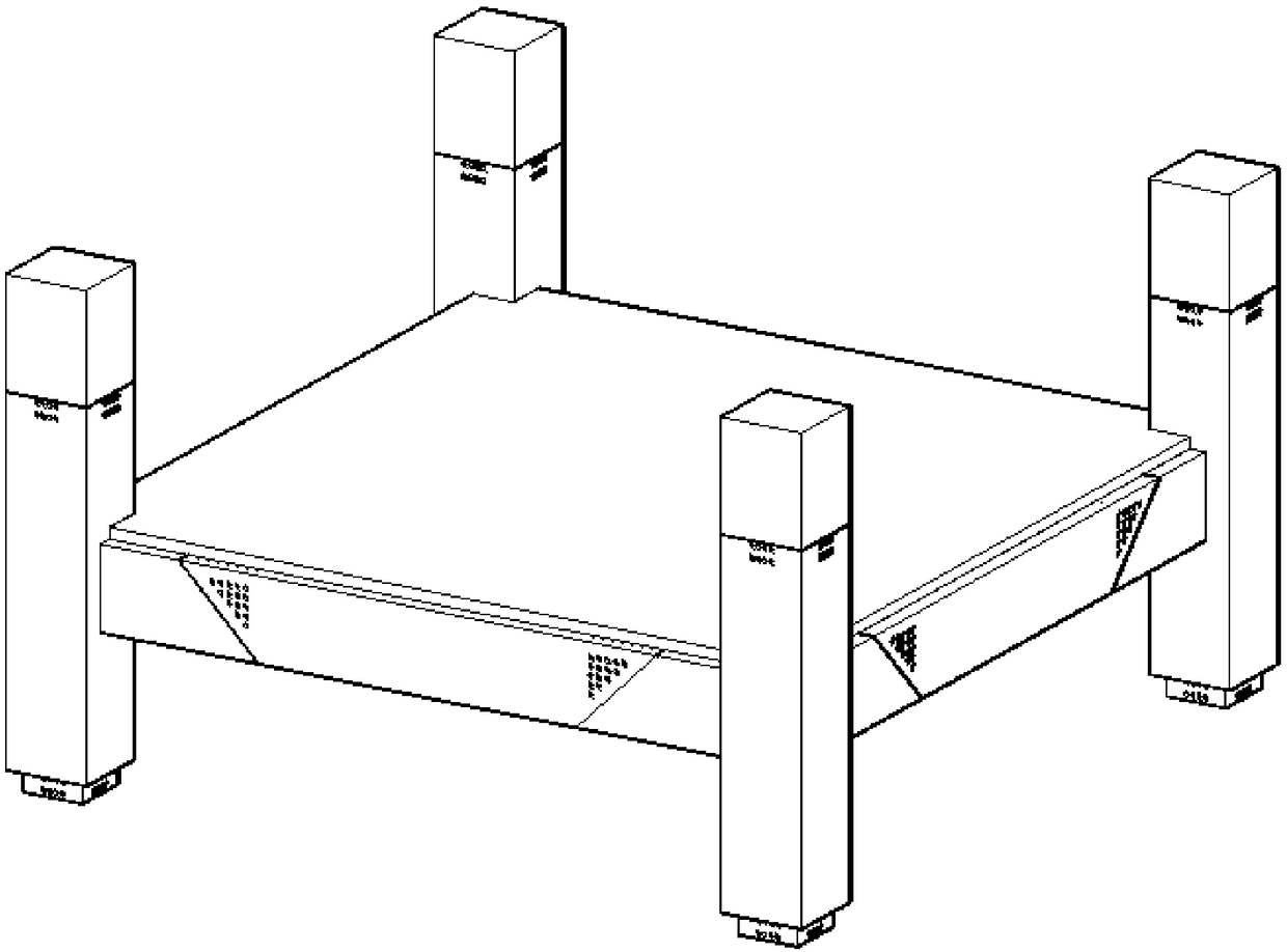
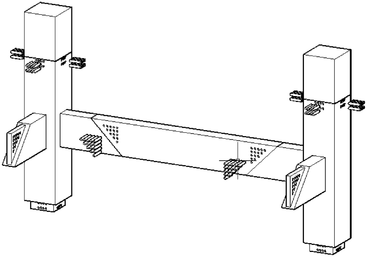
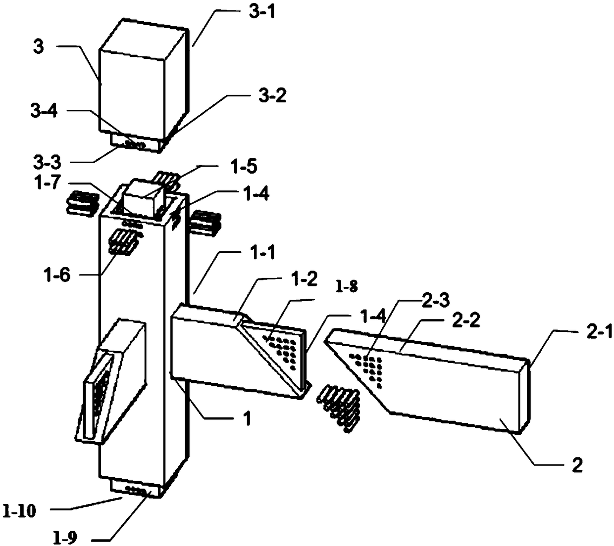
[0036] Such as Figures 1 to 3 As shown, a beam-column node for a prefabricated concrete frame structure includes a node unit 1, a beam unit 2, and a column unit 3. The node unit 1 includes a rectangular concrete column 1-1, which extends along the horizontal direction and is vertically arranged on At least two beam connecting sections 1-2 in the middle of the concrete column 1-1, the upper and lower ends of the concrete column 1-1 and the column unit 3 are provided with matching quick plug-in components and fastened by high-strength bolts; The connection between the beam connection section 1-2 and the beam unit 2 is provided with a matching quick plug assembly and fastened by high-strength bolts, and the connection position between the beam connection section 1-2 and the beam unit 2 is located at 1 / 4 of the middle.

[0037] The size of the concrete column 1-1 is 750*750*3250mm, and its upper end is centered with a first "back"-shaped depression 1-4, and the center of the fir...


PUM


Abstract

The invention discloses a beam-column joint for a fabricated concrete frame structure. The beam-column joint comprises joint units, beam units and column units; the joint units comprise cuboid concrete columns, and two or more beam connecting sections extending in the horizontal direction and vertically arranged in the middles of the concrete columns; quick inserted-connecting assemblies which arematched are arranged at the upper ends and the lower ends of each of the concrete columns and the column units and fastened through high-strength bolts; and quick inserted-connecting assemblies whichare matched are arranged at the junction of the beam connecting sections and the beam units and fastened through high-strength bolts. According to the beam-column joint for a fabricated building, thebeams and the columns are prefabricated as the whole, thus connecting between the beams and the columns and beam-columns are prefabricated together, the strength and stability of component connectionin different directions are improved, the phenomena of weak connection and instable performance between the beams and the columns due to secondary concrete pouring and bolt connection are avoided, the connecting form is simplified, and design of the joint is also simpler and more feasible.

Description

technical field [0001] The patent of the invention is a beam-column joint used in an assembled concrete frame structure. Background technique [0002] At present, concrete construction mainly adopts the method of cast-in-place concrete construction. The method of pouring concrete construction has many advantages, such as: the raw material is cheap, the construction process is more convenient and more reliable. However, there are also some disadvantages. For example, during the construction process, it is necessary to wait for the pouring of concrete for maintenance, which slows down the construction progress; the process of pouring concrete requires the cooperation of multiple workers, which consumes a lot of manpower; It is difficult to achieve precision construction; the construction process of cast-in-place concrete is also easy to cause pollution to the surrounding environment. However, the connection between different components of prefabricated buildings at this stag...

Claims


Application Information

Patent Timeline
Patent Type & Authority Applications(China)
IPC IPC(8): E04B1/20E04B1/21
CPCE04B1/20E04B1/21
Inventor 范学明赵峻鹏钟伟恒具天浩关竣尹
Owner SOUTH CHINA UNIV OF TECH
Why Eureka
Try Eureka