Composite sealing device applied to piston of hydraulic cylinder, and hydraulic cylinder

A combined sealing and hydraulic cylinder technology, applied in the field of hydraulic cylinders, can solve the problems of increased leakage and inability to completely eliminate leakage, and achieve the effect of good sealing performance

Pending Publication Date: 2019-01-29
HUNAN NORMAL UNIVERSITY +1
View PDF5 Cites 7 Cited by
  • Summary
  • Abstract
  • Description
  • Claims
  • Application Information

AI Technical Summary

Problems solved by technology

However, this non-contact gap sealing structure still has some disadvantages, such as the inability to completely eliminate leakage, especially the problem that the amount of leakage increases when

Method used


Image

  • Composite sealing device applied to piston of hydraulic cylinder, and hydraulic cylinder
  • Composite sealing device applied to piston of hydraulic cylinder, and hydraulic cylinder
  • Composite sealing device applied to piston of hydraulic cylinder, and hydraulic cylinder

Examples


Embodiment approach 1

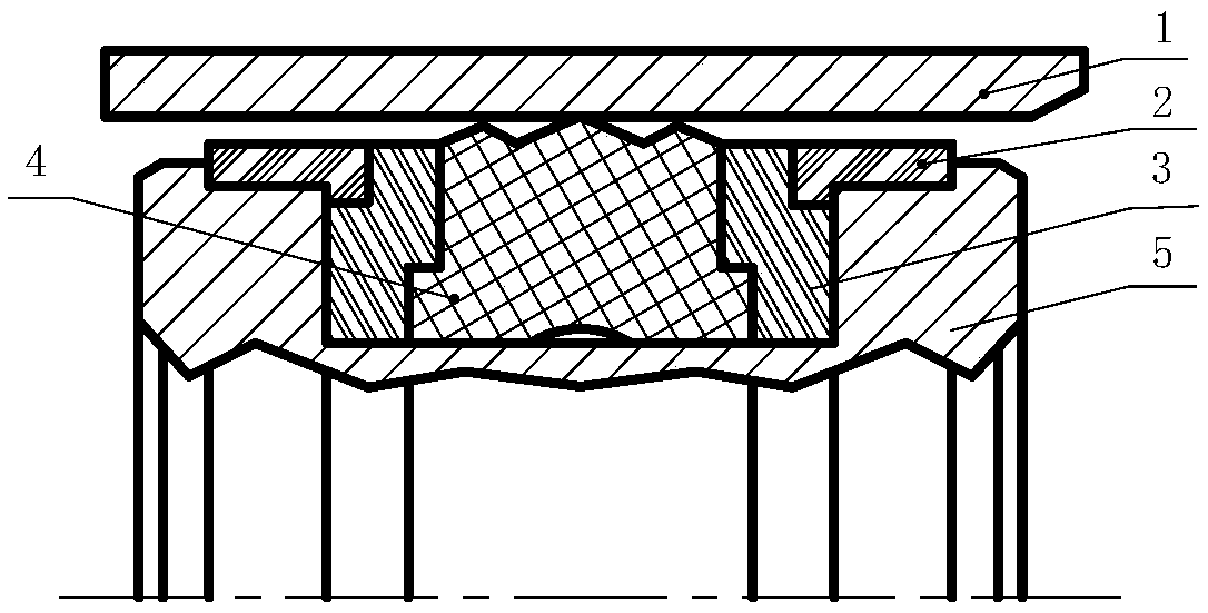
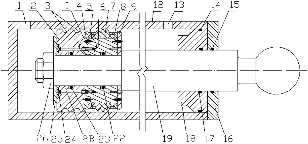
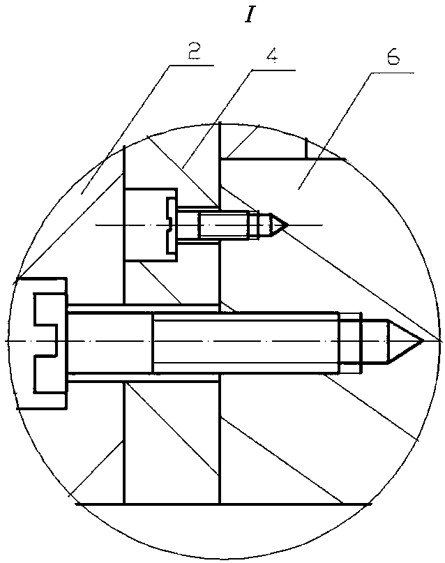
[0035] figure 2 shows a schematic structural diagram of the first embodiment of the present invention, Figure 5-Figure 7 It is a structural diagram of some key parts. Wherein, a combined piston capable of reciprocating linear motion in the hydraulic cylinder is installed in the cylinder 12 of the hydraulic cylinder. The combined piston adopts a split detachable structure and includes a first piston body 2 and a second piston body 6 . The left and right ends of the second piston body 6 are respectively fixed with the first support member 4 and the second support member 9 through screw connection. A flange 9A protrudes outward along the axial direction from the right end of the second support member 9 . The left end of the first support member 4 protrudes outward along the axial direction with a flange 4A, and the right end of the first piston body 2 is recessed with a positioning groove 2A matching the left end flange 4A of the first support member 4 . After the flange 4A ...

Embodiment approach 2

[0042] Figure 4 A schematic structural view of the second embodiment of the present invention is shown, wherein the same parts and components as those of the first embodiment use the same reference numerals as those of the first embodiment. For the sake of brevity, the differences between the second embodiment and the first embodiment are mainly described below. The composition of the combined piston in the second embodiment not only includes the first piston body 2 and the second piston body 6, but also includes the third piston body 11 (see Figure 8 ). There is a small radial gap between the outer surface of the third piston body 11 and the inner wall of the cylinder 12 to form a second gap seal; the outer surface of the third piston body 11 is provided with several second annular pressure equalizing grooves 10 parallel to each other; The left end of the third piston body 11 is concavely provided with a positioning groove 11A matching with the flange 9A at the right end ...


PUM

PropertyMeasurementUnit
Depthaaaaaaaaaa

Abstract

The invention discloses a composite sealing device applied to a piston of a hydraulic cylinder, and the hydraulic cylinder and belongs to the technical field of the hydraulic cylinders. The compositesealing device adopts a separated type piston and comprises at least two piston bodies, wherein a tiny radial clearance exists between the outer edge of a first piston body (2) and the inner wall of acylinder barrel (12) in order to form a first clearance seal; and the outer edge of a second piston body (6) is respectively provided with a sealing part (7), a first retainer ring (5) and a secondretainer ring (8) to form a sealing ring seal. The first piston body (2) and the second piston body (6) are integrally connected with each other through screw threads so as to form a composite piston.The composite piston is integrated with one sealing ring seal and at least one clearance seal in the axial direction so as to form a composite sealing structure. The composite sealing device disclosed by the invention simultaneously adopts the sealing ring seal and the clearance seal to prevent internal leakage, overcomes the shortcomings of the prior art when the sealing ring seal and the clearance seal are used independently, achieves a good sealing effect and is applicable to occasions of which the oil liquid pressure is large and the requirements on the sealing performance are high.

Description

technical field [0001] The invention belongs to the technical field of hydraulic cylinders, and in particular relates to a combined sealing device for hydraulic cylinder pistons and a hydraulic cylinder. Background technique [0002] The hydraulic cylinder is an important executive part in the hydraulic system of construction machinery, and its sealing performance directly affects the working performance of the hydraulic cylinder and even the whole machine. Among them, the seal between the hydraulic cylinder piston and the inner wall of the cylinder barrel is the key sealing link in the hydraulic cylinder, which plays a decisive role in the generation of the typical failure mode of leakage in the hydraulic cylinder. Common sealing devices and structures between the hydraulic cylinder piston and the cylinder mainly include seal ring seals, gap seals and piston ring seals. [0003] "Journal of Central South University" (Natural Science Edition) 2017, Volume 48, Issue 1 "Seali...

Claims


Application Information

Patent Timeline
IPC IPC(8): F15B15/14F15B15/20F16J15/32
CPCF15B15/1452
Inventor 金耀单长征张云涛夏毅敏蔡小艳曾雷史余鹏
Owner HUNAN NORMAL UNIVERSITY
Why Eureka
Try Eureka