A fast opening and closing low torque self-cleaning flat gate valve
A flat gate valve, low torque technology, applied in the field of fast opening and closing low torque self-cleaning flat gate valve, can solve problems such as the gate lift is laborious, the sealing ring is easily damaged, and the effect of reducing the resistance is achieved.
- Summary
- Abstract
- Description
- Claims
- Application Information
AI Technical Summary
Problems solved by technology
Method used
Image
Examples
Embodiment 1
[0041] Embodiments of the present invention are described in detail below, examples of which are shown in the drawings, wherein the same or similar reference numerals designate the same or similar elements or elements having the same or similar functions throughout. The embodiments described below by referring to the figures are exemplary and are intended to explain the present invention and should not be construed as limiting the present invention.
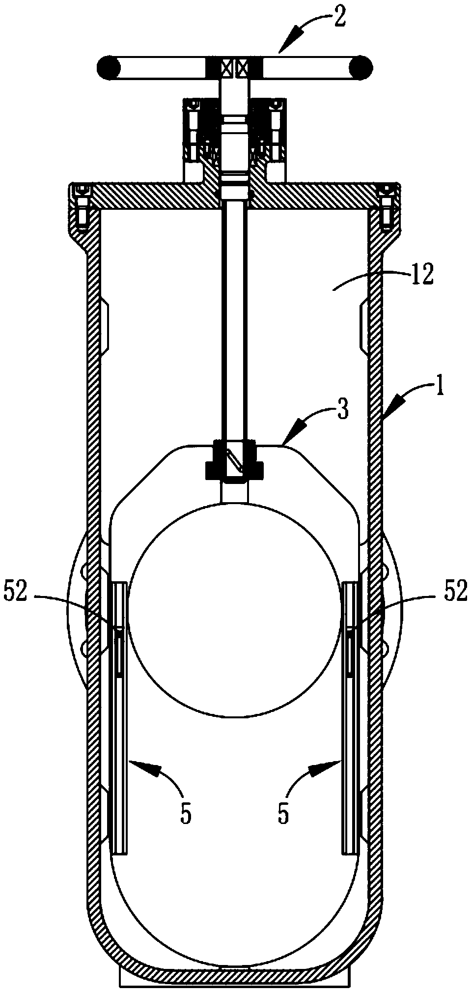
[0042] Such as Figures 1 to 7 As shown, a fast opening and closing low-torque self-cleaning flat gate valve includes a valve body 1 and a lifting mechanism 2 installed inside the valve body 1 and used to control the movement of the gate plate 3 up and down. The valve body 1 is provided with a supply medium The medium passage 11 passing transversely and the valve cavity 12 perpendicular to the medium passage 11 also include:
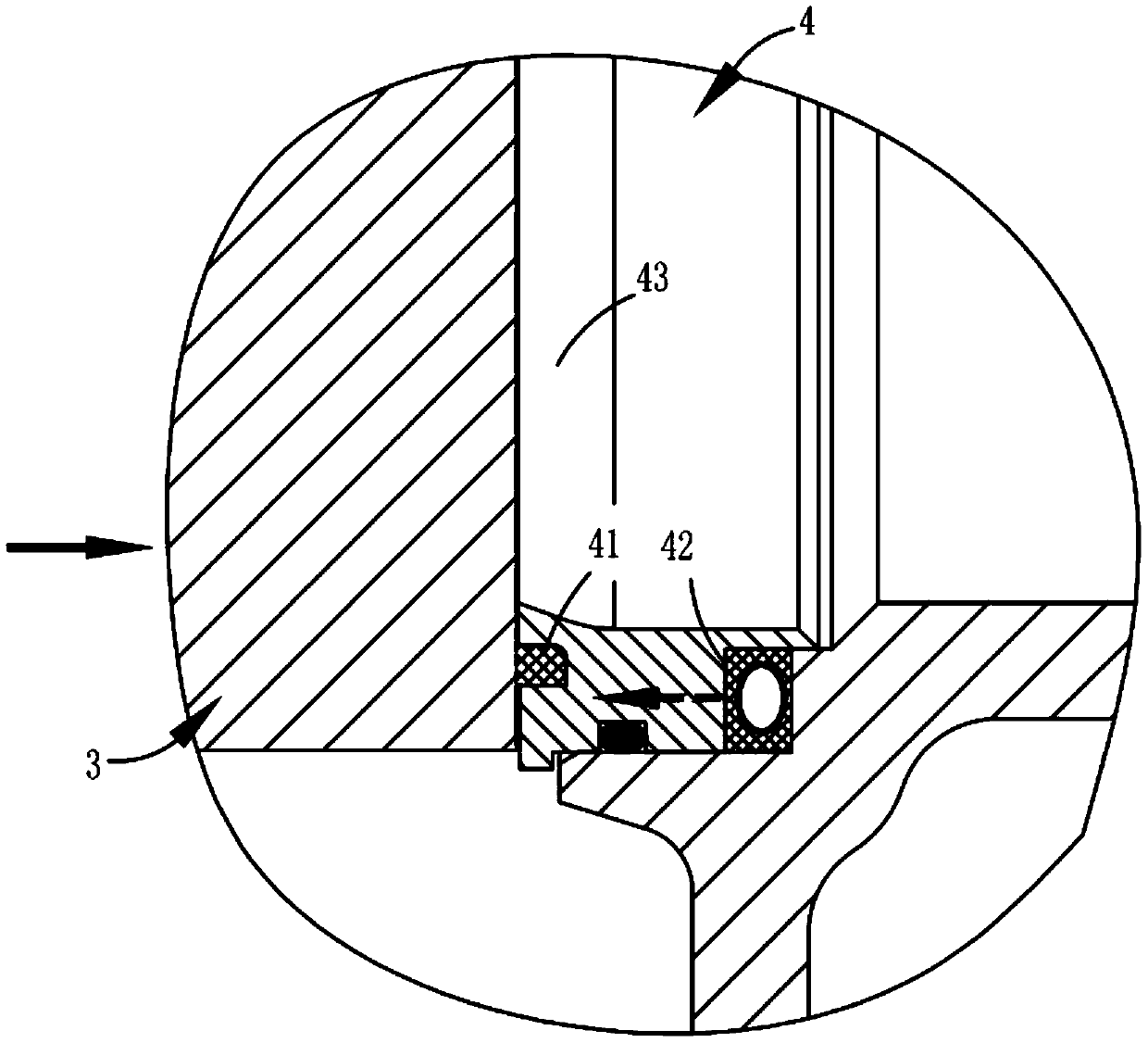
[0043] Valve seat 4, two valve seats 4 are installed in the valve cavity 12, the valve seats 4 are symm...
Embodiment 2
[0051] Such as Figures 8 to 10 As shown, the parts that are the same as or corresponding to those in Embodiment 1 adopt the reference numerals corresponding to Embodiment 1. For the sake of simplicity, only the differences between Embodiment 1 and Embodiment 1 are described below; the differences between Embodiment 2 and Embodiment 1 The difference is that in this embodiment, the lifting mechanism 2 is provided with a ball screw structure, which includes a valve stem 21 and a handwheel 22 , the upper end of the valve stem 21 penetrates to the outside of the valve body 1 and is connected to the handwheel 22 , the valve stem 21 is provided with a spiral raceway, and a nut 23 and a plurality of balls 24 are installed in cooperation;
[0052] Such as Figure 9 and 10 As shown, the gate 3 is a flat plate structure, which is arranged in the valve cavity 12 along the vertical direction, and the upper part of the gate 3 is provided with a diversion hole 31 that is compatible with t...
Embodiment 3
[0058] Such as image 3 and 13 As shown, the parts identical or corresponding to those in the second embodiment adopt the reference numerals corresponding to the second embodiment. For the sake of simplicity, only the differences between the second embodiment and the second embodiment are described below; the difference between the third embodiment and the second embodiment The difference is that the cleaning assembly 43 is fixedly arranged on the inner ring of the valve seat 4 and is located on the side close to the gate plate 3, and the flowing medium in the medium channel 11 is guided to the gate through the cleaning assembly 43. Impurities are cleaned on the surface of the plate 3, and the cleaning component 43 is annular and extends inwardly to provide a transition connection with the internal slope of the valve seat 4. The inner diameter D1 of the cleaning component 43, the inner diameter D2 of the medium channel 11, and the Between the inner diameter D3 and the inner d...
PUM
 Abstract
Description
Claims
Application Information
 - R&D
- Intellectual Property
- Life Sciences
- Materials
- Tech Scout
- Unparalleled Data Quality
- Higher Quality Content
- 60% Fewer Hallucinations
Browse by: Latest US Patents, China's latest patents, Technical Efficacy Thesaurus, Application Domain, Technology Topic, Popular Technical Reports.
© 2025 PatSnap. All rights reserved.Legal|Privacy policy|Modern Slavery Act Transparency Statement|Sitemap|About US| Contact US: help@patsnap.com


