Method for automatically driving vehicles along lane line based on program azimuth angle

An automatic driving and azimuth angle technology, applied in vehicle position/route/height control, two-dimensional position/course control, non-electric variable control, etc., can solve problems that do not conform to human driving habits, and achieve low cost and high efficiency Good, clear physical effect

Inactive Publication Date: 2019-01-29
ZHENGZHOU UNIVERSITY OF LIGHT INDUSTRY
View PDF9 Cites 2 Cited by
  • Summary
  • Abstract
  • Description
  • Claims
  • Application Information

AI Technical Summary

Problems solved by technology

[0004] The purpose of the present invention is to provide a method for automatically driving a vehicle along a lane line based on a program azimuth, which solves the problem in the prior art of using complex calculation controls such as sliding mode control and inversion control based on the precise model of the vehicle and does not meet the requirements. The problem with human driving habits

Method used


Image

  • Method for automatically driving vehicles along lane line based on program azimuth angle
  • Method for automatically driving vehicles along lane line based on program azimuth angle
  • Method for automatically driving vehicles along lane line based on program azimuth angle

Examples


Embodiment 1

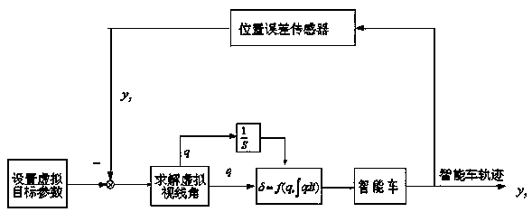
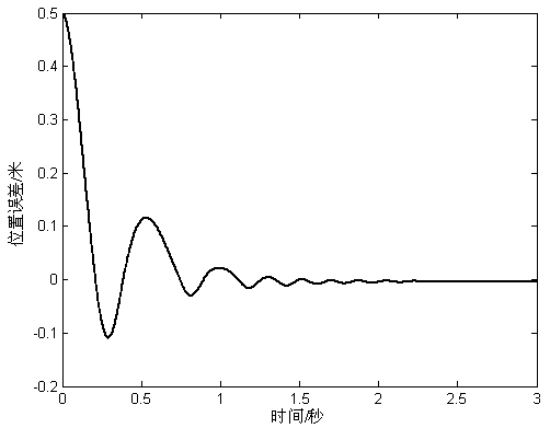
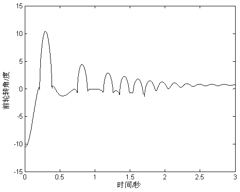
[0037] Example 1. A method for automatic driving of vehicles along lanes based on program azimuth angle, its principle refers to figure 1 , this method uses two position sensors installed on the front and rear bumpers of the vehicle to measure the deviation of the vehicle from the center line of the road, then sets the program moving target on the road center line, and finally calculates the positional relationship between the program moving target and the vehicle Program azimuth, which is similar to the aiming deviation angle calculated by the driver's brain during actual driving. Finally, according to the azimuth, a non-linear proportional integral combination method is used to obtain an automatic driving method for the vehicle to drive along the lane.

[0038] Step 1: Measure the position deviation of the vehicle from the centerline of the road

[0039] Two position sensors installed on the front and rear bumpers of the vehicle are used to measure the position deviation of...

Embodiment 2

[0055] Example 2. A method for automatically driving a vehicle along a lane line based on a program azimuth, the special feature of which is that the method uses two position sensors installed on the front and rear bumpers of the vehicle to measure the deviation of the vehicle from the center line of the road, and then sets the program The moving target is on the center line of the road, and finally the program azimuth is calculated according to the positional relationship between the program moving target and the vehicle. The non-linear proportional-integral combination method obtains the automatic driving method for the vehicle to travel along the lane.

[0056] Step 1: Measure the position deviation of the vehicle from the centerline of the road

[0057] Two position sensors installed on the front and rear bumpers of the vehicle are used to measure the position deviation of the vehicle's lateral position relative to the centerline of the road, and the deviation is recorded...


PUM


Abstract

The invention relates to a method for automatically driving a vehicle along a lane line based on a program azimuth angle. The method includes: using position sensors installed on front and rear bumpers of the vehicle to measure a deviation of the vehicle from a road center line; and then setting a target of the program movement to the road center line; calculating the program azimuth angle according to a positional relationship between the program target and the vehicle; and finally obtaining the automatic driving method of the vehicle along the lane line according to the azimuth angle throughnonlinear proportional integral combination. The method has the advantages that the information to be measured is the least, and only the position deviation of the vehicle is measured, so the implementation is simple and the cost is low; secondly, the program target is used to calculate the program azimuth angle, and the obtained automatic driving law conforms to the thinking habit of the person,the decision-making process of the driver in non-automatic driving is simulated skillfully, therefore, the generated automatic driving law has clear physical meaning, the parameter adjustment is easy, and the obtained automatic driving effect is also good.

Description

technical field [0001] The invention belongs to the field of automatic driving and intelligent transportation, and in particular relates to a method for automatic driving of a vehicle along a lane line based on a program azimuth. Background technique [0002] With the development of unmanned trucks, unmanned buses, unmanned cars, and unmanned ports, vehicle autonomous driving technology has become a hot topic in extensive research in various countries. Among them, the lane line keeping technology, which detects the position deviation between the vehicle and the lane line and uses automatic control technology to eliminate the deviation, has become the core technology in the automatic driving technology. At present, the existing vehicle automatic driving technology is implemented based on the precise model of the vehicle using technical means such as sliding mode control and inversion control. This method is different from the driving habits of people in real life. First of a...

Claims


Application Information

Patent Timeline
Patent Type & Authority Applications(China)
IPC IPC(8): G05D1/02
CPCG05D1/021
Inventor 马照瑞李霞王浩乔伟涛周宏伟雷军委
Owner ZHENGZHOU UNIVERSITY OF LIGHT INDUSTRY
Why Eureka
Try Eureka