Eureka AIR delivers breakthrough ideas for toughest innovation challenges, trusted by R&D personnel around the world.

Coat hanger for garment machining

A technology of machinery and clothing, applied in the direction of hangers, clothing, applications, etc., can solve the problems of increased inconvenience

Active Publication Date: 2019-02-01
童小鸾
View PDF5 Cites 3 Cited by
  • Summary
  • Abstract
  • Description
  • Claims
  • Application Information

AI Technical Summary

Problems solved by technology

"Clothes hangers" are a major feature product in China. The industry has been formed for more than ten years, and the technology has been continuously improved and changed since its inception. Now the ordinary clothes hangers need to be completely removed or lowered in the later process of collecting clothes. It can only be removed at a position where people can reach it, which increases the inconvenience of use

Method used


Image

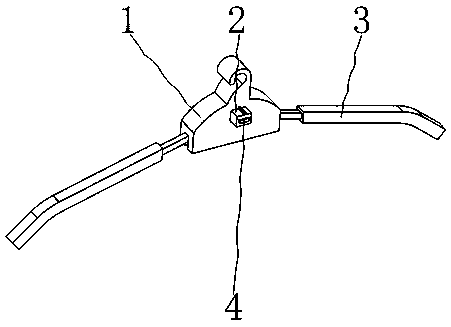
  • Coat hanger for garment machining
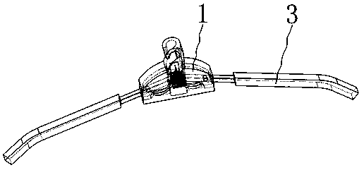
  • Coat hanger for garment machining
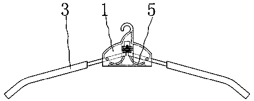
  • Coat hanger for garment machining

Examples


specific Embodiment approach

[0048] The specific embodiment: when using the clothes hanger designed by the present invention, when people are hanging clothes, they will hang the clothes on the clothes hanger gently at first, but their hands will drag the clothes, and now the clothes support bar 3 will be given to it by the clothes. A pressure, the clothes support bar 3 will swing downward, and the swing of the clothes support bar 3 will squeeze the limit block 7, so that the limit block 7 slides along the second guide groove 26, and the slide of the limit block 7 will drive the first One rack 19 moves, and the first rack 19 moves and will drive the second gear 31 that meshes with it to rotate, and the second gear 31 rotates to drive the rotation shaft 32 to rotate, and the rotation of the rotation shaft 32 drives the first gear 29 to rotate, and the first gear 29 The rotation will drive the second rack 20 to move, and the movement of the second rack 20 will drive the marking plate 30 installed on it to mov...


PUM


Abstract

The invention belongs to the technical field of coat hangers, and particularly relates to a coat hanger for garment machining. The coat hanger comprises an installing block, a coat hanging rod and anadjusting rod; when a person hangs a garment, firstly, the garment is slightly hung to the coat hanger, the hand can support the garment, at the moment, the coat hanging rod can bear pressure given bythe garment, the coat hanging rod can swing downwards, the coat hanging rod swings so that a marking plate can move, the moving amount of a limiting block is determined according to the position relation of the marking plate and a mark block on the marking block, the adjusting rod is adjusted according to the moving amount of a limiting block, and then the extrusion force of a first spring borneby the limiting block is adjusted; in the adjusting process, the adjusting rod is adjusted while the garment is placed down, finally, the extrusion force of the first spring borne by the limiting block is large enough to bear the weight of the garment, after the garment is aired, the garment is pulled downwards so that the limiting block and the coat hanging rod can be disengaged, after the coat hanging rod swings by a certain angle, the garment can be taken down, and the garment obtaining time is shortened.

Description

Technical field [0001] The invention belongs to the technical field of clothes hangers, in particular to a clothes hanger for clothing machinery. Background technique [0002] Clothes hangers, as household items that people use every day, have become a daily necessity in many families. "Clothes hangers" are a major feature product in China. The industry has been formed for more than ten years, and the technology has been continuously improved and changed since its inception. Now the ordinary clothes hangers need to be completely removed or lowered in the later process of collecting clothes. It can only be taken off at a position that people can reach, which increases the inconvenience of use. [0003] The present invention designs a clothes hanger for clothing machinery to solve the above problems. Contents of the invention [0004] In order to solve the above-mentioned defects in the prior art, the present invention discloses a clothes hanger for clothing machinery, whi...

Claims


Application Information

Patent Timeline
IPC IPC(8): A47G25/14A47G25/44
CPCA47G25/44
Inventor 李少枝童小鸾
Owner 童小鸾
Why Eureka
Eureka Blog
Learn More