Novel fully-automatic spiral tube coiling machine

A fully automatic, pipe coiling machine technology, applied in the field of pipe coiling machines, can solve the problems of pipe coiling machine consumption, inability to adjust the degree of bending of steel pipes, trouble, etc., and achieve the effect of saving manpower and increasing practicability

Inactive Publication Date: 2019-02-01
温州柔美机械科技有限公司
View PDF0 Cites 0 Cited by
  • Summary
  • Abstract
  • Description
  • Claims
  • Application Information

AI Technical Summary

Problems solved by technology

[0002] The pipe coiling machine is a common tool used to bend the steel pipe. In the existing construction industry, people often need to bend the steel pipe to a certain extent for use. At this time, the pipe coiling machine needs to be used to process the steel pipe. During the processing, Manpower is needed for assistance; the existing coiling machine has certain disadvantages in use. First, the existing coiling machine needs to consume more manpower in use, which is troublesome. Secondly, it cannot be adjusted according to the specifications of the steel pipe. There are certain limitations. Finally, the bending degree of the steel pipe cannot be adjusted accurately, which has a certain impact on people's use process. For this reason, we propose a new type of fully automatic spiral coiling machine

Method used

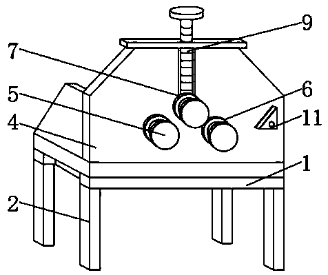
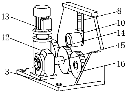
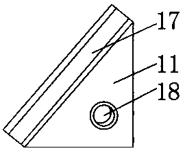

Image

  • Novel fully-automatic spiral tube coiling machine
  • Novel fully-automatic spiral tube coiling machine
  • Novel fully-automatic spiral tube coiling machine

Examples


Embodiment Construction

[0017] In order to make the technical means, creative features, goals and effects achieved by the present invention easy to understand, the present invention will be further described below in conjunction with specific embodiments.

[0018] In the description of the present invention, it should be noted that the terms "upper", "lower", "inner", "outer", "front end", "rear end", "both ends", "one end", "another end" The orientation or positional relationship indicated by etc. is based on the orientation or positional relationship shown in the drawings, and is only for the convenience of describing the present invention and simplifying the description, rather than indicating or implying that the referred device or element must have a specific orientation, use a specific Azimuth configuration and operation, therefore, should not be construed as limiting the invention. In addition, the terms "first" and "second" are used for descriptive purposes only, and should not be understood ...


PUM


Abstract

The invention discloses a novel fully-automatic spiral tube coiling machine. The novel fully-automatic spiral tube coiling machine comprises a main frame, wherein the four corners of the bottom end ofthe main frame are welded with foot stools which are arranged in the form of a rectangle; the top end of the main frame is fixedly equipped with a bottom plate through a bolt; the top end of the mainframe is fixedly equipped with a mounting plate; the bottom end of the mounting plate is welded with the top end of the bottom plate; a tube coiling shaft I is arranged in front of the mounting plate; a tube coiling shaft II is arranged on a position, close to one side of the mounting plate, in front of the mounting plate; a tube coiling shaft III is arranged above a position, between the tube coiling shaft I and the tube coiling shaft II, in front of the mounting plate; and an open slot is formed in a position, above the tube coiling shaft III, inside the mounting plate. The novel fully-automatic spiral tube coiling machine disclosed by the invention is equipped with a knob, a transmission box and a screw, so that curvature of a steel tube can be regulated better, a great deal of labourpower is saved, applicability of equipment is increased, and a better use prospect is brought.

Description

technical field [0001] The invention relates to the field of coiling machines, in particular to a novel fully automatic spiral coiling machine. Background technique [0002] The pipe coiling machine is a common tool used to bend the steel pipe. In the existing construction industry, people often need to bend the steel pipe to a certain extent for use. At this time, the pipe coiling machine needs to be used to process the steel pipe. During the processing, Manpower is required for assistance; the existing coiling machine has certain disadvantages in use. Firstly, the existing coiling machine needs to consume more manpower in use, which is troublesome. Secondly, it cannot be adjusted according to the specifications of the steel pipe. There are certain limitations. Finally, the bending degree of the steel pipe cannot be adjusted accurately, which has a certain impact on people's use process. Therefore, we propose a new type of fully automatic spiral coiling machine. Contents ...

Claims


Application Information

Patent Timeline
Patent Type & Authority Applications(China)
IPC IPC(8): B21D7/08
CPCB21D7/08
Inventor 梅楼建胡国华陈静玉
Owner 温州柔美机械科技有限公司
Why Eureka
Try Eureka