Magnetic resonance imaging control device for movement

A magnetic resonance imaging and control device technology, which is applied in medical science, diagnosis, diagnostic recording/measurement, etc., can solve problems such as inability to adjust at will, low accuracy of position repeatability, and inability to guarantee the efficiency and accuracy of motion imaging, etc. question

Inactive Publication Date: 2010-09-29
SIEMENS HEALTHINEERS LTD
View PDF1 Cites 0 Cited by
  • Summary
  • Abstract
  • Description
  • Claims
  • Application Information

AI Technical Summary

Problems solved by technology

[0006] To sum up, this neck motion MRI control method is cumbersome and inefficient, and the adjustment range of the curvature of the subject’s neck cannot be precisely controlled and cannot be adjusted at will, and the accuracy of position repeatability is not good. High, so the efficiency and accuracy of its motion imaging cannot be guaranteed

Method used


Image

  • Magnetic resonance imaging control device for movement
  • Magnetic resonance imaging control device for movement
  • Magnetic resonance imaging control device for movement

Examples


no. 1 example

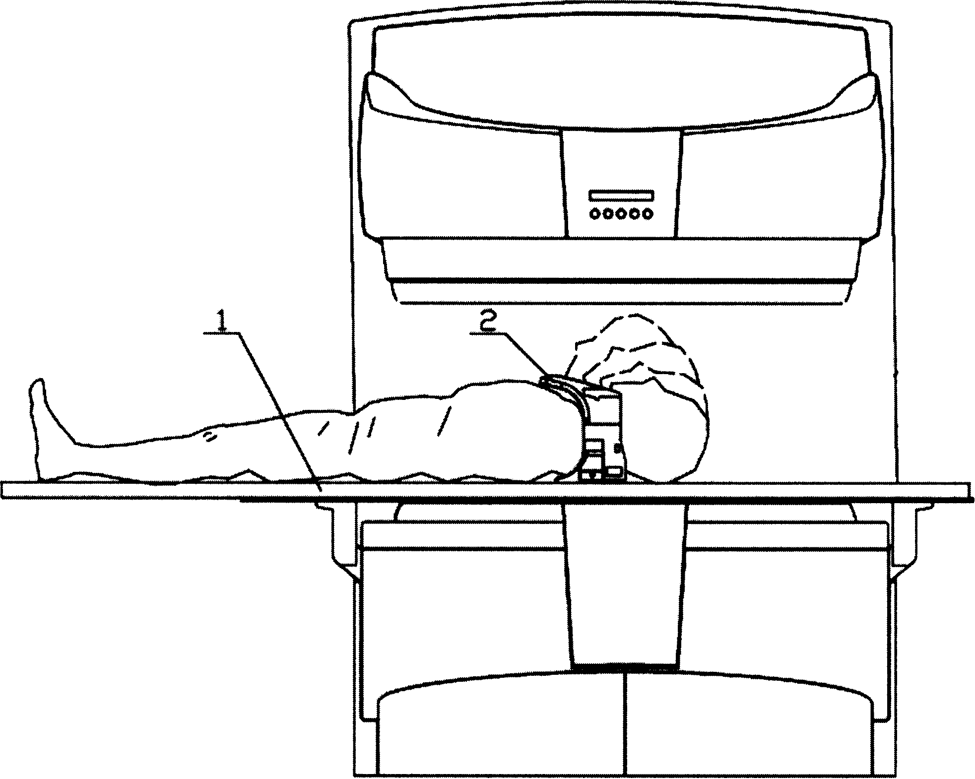
[0026] Figure 2 to Figure 6 It shows the structure of the first embodiment of the motion magnetic resonance imaging control device of the present invention and its application in the magnetic resonance imaging system. Within this limit, the motion magnetic resonance imaging control device of the present invention can also be applied to motion imaging of other imaging parts of the inspection object such as joint motion imaging.

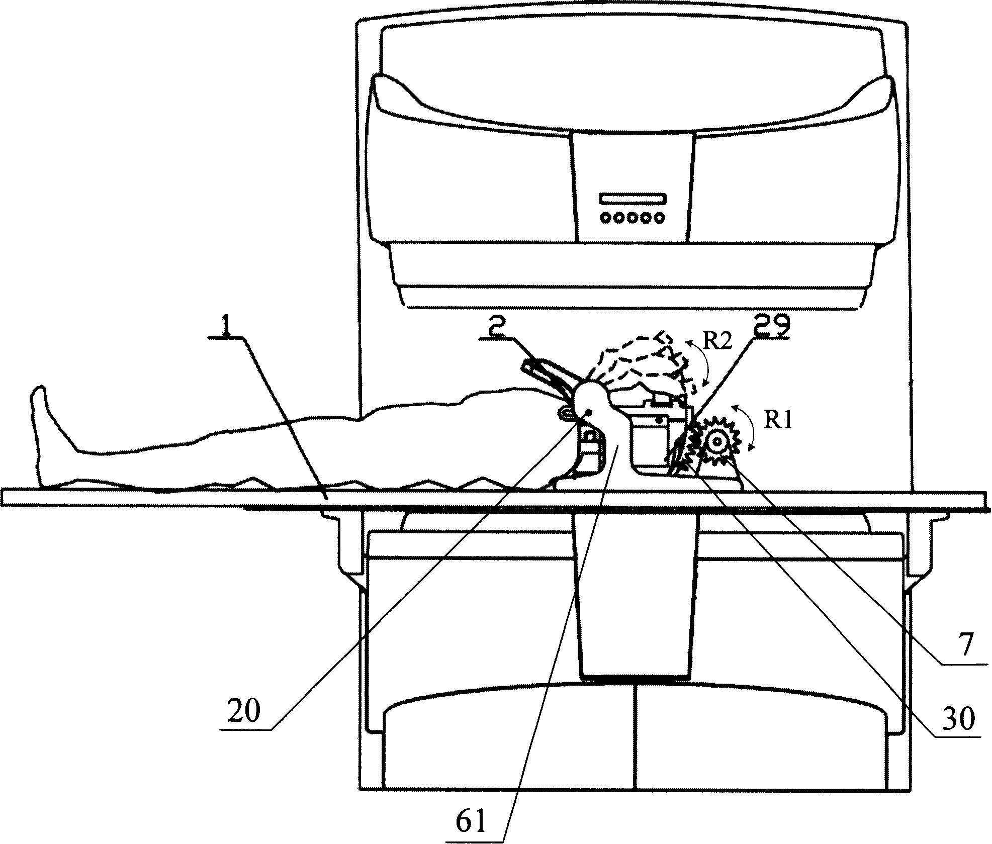
[0027] refer to figure 2 , the motion magnetic resonance imaging control device includes a support 61 on which the rotating shaft 20 is arranged. Wherein, the rotating shaft 20 is arranged between the rotating shaft holes of the supporting arms extending upward from both sides of the support 61 .

[0028] A bracket 29 for supporting an imaging part of an inspection object, such as a head, is disposed on the support 61 and is rotatable around the rotation axis 20 . The bracket 29 is usually U-shaped to effectively accommodate the head of the test o...

no. 2 example

[0034] The motion magnetic resonance imaging control device of this embodiment is basically the same as that of the first embodiment, except that the motor 9 does not directly drive the transmission gear 7 through its output shaft, but A synchronous belt 8 is arranged between the transmission gear 7 and the transmission gear is driven by the synchronous belt 8 . Similarly, in this embodiment, the application in neck motion imaging is used as an example for illustration, and it is not limited thereto. The motion magnetic resonance imaging control device of the present invention can also be applied to other imaging of inspection objects such as joint motion imaging. In motion imaging of parts.

[0035] refer to Figure 7 , this figure shows the situation that the motion magnetic resonance imaging control device described in this embodiment is applied in a low-field magnetic resonance system, wherein the support 61 is fixed on the hospital bed 1, and the head of the examination ...

no. 3 example

[0038] Figure 9 to Figure 12 A schematic diagram showing the structure and application of the third embodiment of the motion magnetic resonance imaging control device of the present invention. Similarly, in this embodiment, the application in neck motion imaging is used as an example for illustration, and it is not limited thereto. The motion magnetic resonance imaging control device of the present invention can also be applied to other imaging of inspection objects such as joint motion imaging. In motion imaging of parts.

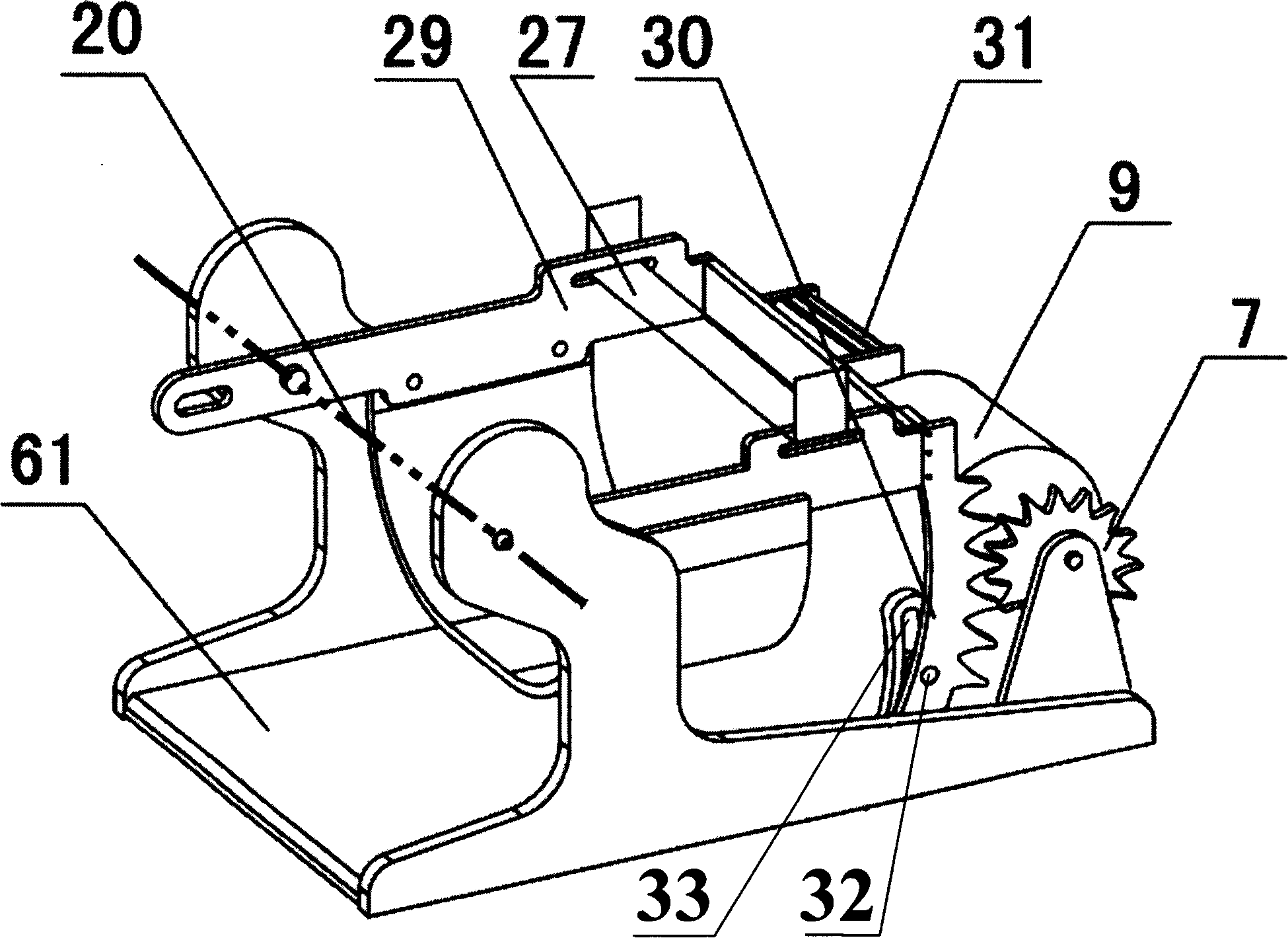
[0039] refer to Figure 9 and Figure 10 , The motion magnetic resonance imaging control device of this embodiment also includes the above-mentioned bracket 61 having the rotation shaft 20, and the bracket 29 that rotates around the rotation shaft 20 and is used to support the head of the examinee. The linkage 26 is fixedly connected to the bracket 29, and when the bracket 29 is driven by a driving source, such as manually driven, and rotates around th...


PUM


Abstract

The present invention provides a motion magnetic resonance imaging control device used for adjusting the imaged position bending degree of a checked object. The invention comprises a bracket that revolves around a rotation axis and the bracket supports the imaged position of a checked object; an interlinkage piece that is fixedly connected with the bracket; and a driving source for driving the interlinkage piece to cause the bracket to revolve around the rotation axis. The magnetic resonance system uses the motion magnetic resonance imaging control device for imaging a motion; especially whenimaging and scanning a neck motion, the neck bending degree and the position of the checked object can be controlled in real time. On the basis of actual need, a doctor can manually (or activate a corresponding order on a control equipment) control the driving source for precisely and gradually changing a checked object neck bending degree within an adjusting range; or on the basis of actual need, the doctor precisely sets a checked object neck bending degree, and precisely reverts to any neck bending status when necessary.

Description

technical field [0001] The invention relates to a magnetic resonance imaging device, in particular to a motion magnetic resonance imaging control device. Background technique [0002] Magnetic resonance motion imaging, especially cervical motion magnetic resonance imaging, provides a method for functional determination of the cervical spine, which can be used in the diagnosis of position-dependent lesions, spinal cord stenosis, occult dislocation, or other types of functional lesions in the occipital and cervical spine. , is a classic evaluation criterion for qualitative judgment. [0003] In cervical motion magnetic resonance imaging, qualitative and positioning information can be obtained by accurately displaying the relationship between the spinal cord, intervertebral disc, and vertebral body. Anomalies found. [0004] When performing neck motion magnetic resonance imaging on the subject, due to the influence of the anatomical structure, doctors often need to repeatedly...

Claims


Application Information

Patent Timeline
Patent Type & Authority Patents(China)
IPC IPC(8): A61B5/055
Inventor 薛廷强葛志柏贺增合邢旭光
Owner SIEMENS HEALTHINEERS LTD
Why Eureka
Try Eureka