
Combined exhaust cooling system of laser cutting device

A cooling system and laser cutting technology, applied in auxiliary devices, embroidery machine mechanisms, embroidery machines, etc., can solve the problems of optical fiber performance attenuation, harm to the human respiratory system, and inability to discharge smoke outdoors, and achieve the effect of performance protection.

Active Publication Date: 2014-11-05
上工富怡智能制造(天津)有限公司
View PDF8 Cites 0 Cited by
  • Summary
  • Abstract
  • Description
  • Claims
  • Application Information

AI Technical Summary

Problems solved by technology

[0002] When the laser cutting machine cuts materials, it will produce a large amount of toxic gas. If it is not handled properly, it will cause harm to the human respiratory system.
[0003] Chinese patent ZL201120347320.6 discloses a computer laser embroidery machine, which includes a laser cutter head, an optical fiber for transmitting laser light, and a smoke exhaust pipe device. The optical fiber is connected to the laser cutter head, and laser cutting or embroidery is performed on the workbench. On the top cover of the embroidery machine (not shown in the figure), the smoke generated by the laser cutter head cutting or embroidery cannot be directly discharged outside
[0004] More importantly, the optical fiber transmission line is long, and excessive bending of the optical fiber will degrade the performance of the optical fiber
At the same time, during long-term operation, the optical fiber generates a lot of heat during operation, which affects the service life of the optical fiber

Method used


Image

  • Combined exhaust cooling system of laser cutting device

Examples


Embodiment Construction

[0020] Below, the present invention will be described in further detail in conjunction with the accompanying drawings and specific embodiments.

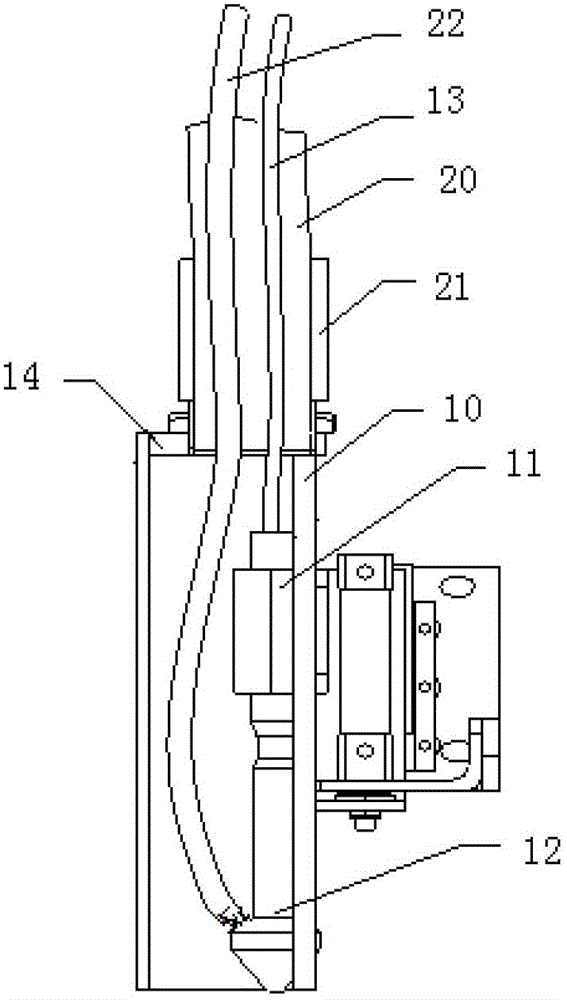
[0021] figure 1 It is a schematic diagram of the composite exhaust air cooling system of the laser cutting device of the present invention. As shown in the figure, the composite exhaust air cooling system of the laser cutting device includes: a laser cutter head 12 for cutting or embroidery, an optical fiber 13 for transmitting laser light, and a smoke exhaust pipe 10 that generates smoke when discharging cutting materials. The laser cutter head 12 is arranged on the In the smoke exhaust pipe 10, an air duct plug 21 is formed on the upper baffle plate 14 of the smoke exhaust pipe. One end of the air duct 20 is connected to the exhaust pipe 10 through the air duct plug 21, and the other end of the air duct 20 is connected to the air duct pipe. , thus, the laser cutter head is set to work in a closed space, and the smoke generated whe...


PUM


Abstract

The invention discloses a combined exhaust cooling system of a laser cutting device. The combined exhaust cooling system of the laser cutting device comprises an exhaust bucket. A laser tool head holder is arranged in the exhaust bucket, and a laser tool head is fixed on the laser tool head holder. An air tube plug is formed on an upper baffle plate of the exhaust bucket. One end of an air pipe duct is hermetically connected with the exhaust bucket through the air pipe plug. The other end of the air pipe duct extends outdoors. An optical fiber is connected with the laser tool head through the air pipe duct. Cold air is blown in towards the laser tool head to improve cooling effect, and a blow pipe is connected with the laser tool head through the air pipe duct. The combined exhaust cooling system has the advantages that flexibility of the optical fiber is effectively controlled through the air pipe duct, and properties of the optical fiber are protected; the air pipe duct is hermetically connected with the exhaust bucket, and exhaust flow from the exhaust bucket is discharged through the air pipe duct and cools the optical fiber.

Description

technical field [0001] The invention relates to a laser computerized embroidery machine, in particular to an exhaust cooling device of the laser computerized embroidery machine. Background technique [0002] When the laser cutting machine cuts materials, it will produce a large amount of toxic gas. If it is not handled properly, it will cause harm to the human respiratory system. [0003] Chinese patent ZL201120347320.6 discloses a computer laser embroidery machine, which includes a laser cutter head, an optical fiber for transmitting laser light, and a smoke exhaust pipe device. The optical fiber is connected to the laser cutter head, and laser cutting or embroidery is performed on the workbench. On the top cover of the embroidery machine (not shown in the figure), the smoke generated during cutting or embroidery by the laser cutter head cannot be directly discharged outside. [0004] More importantly, the optical fiber conduction line is long, and excessive bending of the...

Claims


Application Information

Patent Timeline
Patent Type & Authority Patents(China)
IPC IPC(8): D05C13/00D05C7/10
Inventor 鲍胜群
Owner 上工富怡智能制造(天津)有限公司
Learn More