Welding joint and use method thereof

A technology for welding joints and welding wires, applied in the field of fish scale welding, which can solve the problems of slow production efficiency and high salary costs

Inactive Publication Date: 2019-02-01
杭州西非电子信息技术有限公司
View PDF0 Cites 3 Cited by
  • Summary
  • Abstract
  • Description
  • Claims
  • Application Information

AI Technical Summary

Problems solved by technology

[0002] At present, most of the welding in the market is manually controlled. Although it has high precision and good effects, the production efficiency is relatively slow, and most of the fish scale welding can only be completed by welders with certain work experience. Training manual labor requires a lot of labor and skilled Local technicians need to spend a lot of salary to hire, so fully automatic welding machines are very in-demand machines

Method used


Image

  • Welding joint and use method thereof

Examples


Embodiment Construction

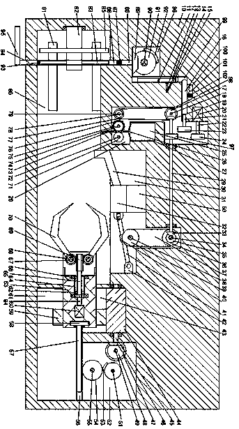
[0016] Such as figure 1 As shown, a welded joint of the present invention and its use method include a frame 10, a processing cavity 80 is provided in the frame 10, and a connected pole cavity 31 is provided above the processing cavity 80. The upper end wall of the pole chamber 31 is provided with a connected belt chamber 37, and the frame 10 is provided with a transmission chamber 28 on the left side of the pole chamber 31, and the left side of the transmission chamber 28 is provided with a connected sliding belt chamber. cavity 99, the left side of the sliding cavity 99 is provided with a first gear cavity 96, the frame 10 is provided with a clamping cavity 61 on the right side of the processing cavity 80, and the upper end of the clamping cavity 61 is provided with a third Gear chamber 43, the right side of the third gear chamber 43 is provided with a second gear chamber 52, the lower end wall of the processing chamber 80 is rotated and provided with a handle 94, and a hand...


PUM


Abstract

The invention relates to a welding joint and a use method thereof. The welding joint comprises a rack; the rack is internally provided with a machining cavity, an electric pole cavity communicating with the machining cavity is formed in the upper part of the machining cavity, a belt cavity communicating with the electric pole cavity is formed in the upper end wall of the electric pole cavity, therack is internally provided with a transmission cavity located on the left side of the electric pole cavity, a sliding cavity communicating with the transmission cavity is formed in the left side of the transmission cavity, a first gear cavity is formed in the left side of the sliding cavity, the rack is internally provided with a clamping claw cavity in the right side of the machining cavity, a third gear cavity is formed in the upper end face of the clamping claw cavity, a second gear cavity is formed in the right side of the third gear cavity, a rotating handle is rotatably arranged on thelower end wall of the machining cavity, a grip handle is fixedly arranged on the lower part of the rotating handle, a magnet is fixedly arranged at the top end of the rotating handle, the machining cavity is internally provided with a clamping block, and a fixing frame is rotatably arranged on the left end wall of the machining cavity.

Description

technical field [0001] The invention relates to scale welding of technical parts, in particular a welded joint and a method for its use. Background technique [0002] At present, most of the welding in the market is manually controlled. Although it has high precision and good effects, the production efficiency is relatively slow, and most of the fish scale welding can only be completed by welders with certain work experience. Training manual labor requires a lot of labor and skilled Local technicians need to spend a lot of salary to hire, so fully automatic welding machines are very in-demand machines. Contents of the invention [0003] Aiming at the deficiencies of the above technologies, the present invention proposes a welded joint and its usage method. [0004] A welded joint and its use method of the present invention, comprising a frame, a processing cavity is arranged inside the frame, a connected electric pole cavity is arranged above the processing cavity, and th...

Claims


Application Information

Patent Timeline
Patent Type & Authority Applications(China)
IPC IPC(8): B23K31/02B23K37/02B23K37/04
CPCB23K31/02B23K37/02B23K37/04
Inventor 程松涛
Owner 杭州西非电子信息技术有限公司
Why Eureka
Try Eureka