Environment-friendly biomass fuel pretreatment processing device
A biomass fuel and processing device technology, applied in the direction of biofuel, waste fuel, fuel, etc., can solve the problem that biomass fuel cannot be distributed according to equal weight, so as to facilitate processing or packaging, prevent overload, and prolong service life Effect
- Summary
- Abstract
- Description
- Claims
- Application Information
AI Technical Summary
Problems solved by technology
Method used
Image


Examples
specific Embodiment approach 1
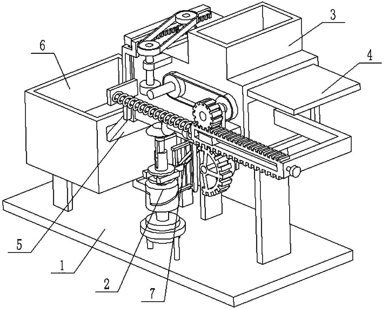
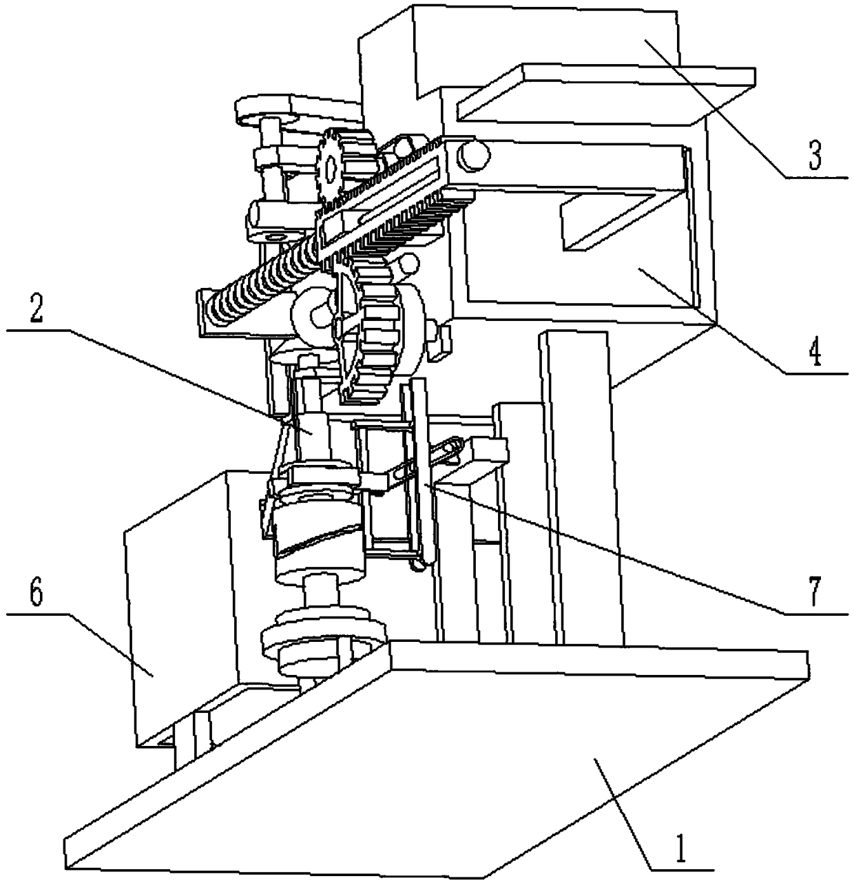
[0032] Combine below Figure 1-15 Describe this embodiment, an environment-friendly biomass fuel pretreatment processing device, including a base 1, a transmission wheel 2, a fuel processing box 3, a pushing plate 4, an inclined plate 5, a collection box 6 and a linkage plate 7, the The fuel processing box 3 and the collection box 6 are all fixedly connected on the base 1, the inclined plate 5 is fixedly connected between the fuel processing box 3 and the collection box 6, and the pushing plate 4 is slidably connected on the fuel processing box 3, pushing The material plate 4 is connected to the fuel processing box 3 by transmission, the two ends of the transmission wheel 2 are respectively connected to the pusher plate 4 and the base 1 by transmission, the transmission wheel 2 is fixedly connected to the base 1, and the linkage plate 7 is slidably connected to the collection box 6 , The linkage plate 7 is matched with the middle end clearance of the drive wheel 2. The base 1...
specific Embodiment approach 2
[0033] Combine below Figure 1-15 To illustrate this embodiment, the base 1 includes a base plate 1-1, a support plate 1-2, a motor 1-3 and a power transmission wheel I1-4; both support plates 1-2 are fixedly connected to the base plate 1-1. At the right end, the motor 1-3 is fixedly connected to the base plate 1-1 through the motor frame, the power transmission wheel I1-4 is fixedly connected to the output shaft of the motor 1-3, and the power transmission wheel I1-4 is connected to the transmission wheel 2 in transmission. When the base 1 is in use, the motor 1-3 is connected to the power supply and the control switch through wires and turned on, the motor 1-3 drives the power transmission wheel I1-4 to rotate counterclockwise around its own axis, and the power transmission wheel I1-4 drives the transmission Wheel 2 works.
specific Embodiment approach 3
[0034] Combine below Figure 1-15 To illustrate this embodiment, the transmission wheel 2 includes a power transmission wheel II 2-1, a telescopic shaft 2-2, a sheave 2-3, a compression spring I 2-4, a shaft sleeve 2-5, a driving bevel gear 2-6 and The telescopic shaft frame 2-7; the power transmission wheel II 2-1 is connected to the power transmission wheel I1-4, and the power transmission wheel II 2-1 and the sheave 2-3 are respectively fixedly connected to the lower end and the middle end of the telescopic shaft 2-2, The sheave 2-3 is in clearance fit with the linkage plate 7, the shaft sleeve 2-5 is slidably connected to the upper end of the telescopic shaft 2-2, the upper end of the telescopic shaft 2-2 is provided with a raised groove, and the shaft sleeve 2-5 is fixedly connected with The convex line, the space between the convex line fits in the convex line groove, the compression spring I2-4 is fixedly connected between the shaft sleeve 2-5 and the telescopic shaft 2...
PUM
 Abstract
Description
Claims
Application Information
 - R&D
- Intellectual Property
- Life Sciences
- Materials
- Tech Scout
- Unparalleled Data Quality
- Higher Quality Content
- 60% Fewer Hallucinations
Browse by: Latest US Patents, China's latest patents, Technical Efficacy Thesaurus, Application Domain, Technology Topic, Popular Technical Reports.
© 2025 PatSnap. All rights reserved.Legal|Privacy policy|Modern Slavery Act Transparency Statement|Sitemap|About US| Contact US: help@patsnap.com