Complete equipment of turbine

A complete set of equipment, steam turbine technology, applied in the direction of mechanical equipment, engine components, machines/engines, etc., can solve the problems of inconvenient replacement of impeller sets for work efficiency, increased maintenance costs, and damage to turning motors, so as to improve work efficiency and structure Simple, easy-to-use effect

Inactive Publication Date: 2019-02-01
余连平
View PDF0 Cites 0 Cited by
  • Summary
  • Abstract
  • Description
  • Claims
  • Application Information

AI Technical Summary

Problems solved by technology

The existing cranking devices in steam turbines are generally manually monitored or monitored by the computer, and there is a certain delay. If the output shaft cannot be disengaged in time, it will cause irreversible damage to the cranking motor and increase maintenance costs.
At the same time, the angle of the impeller of the traditional steam turbine is fixed, and it is very inconvenient to replace the impeller group as a whole when the work efficiency needs to be changed.

Method used


Image

  • Complete equipment of turbine
  • Complete equipment of turbine

Examples


Embodiment Construction

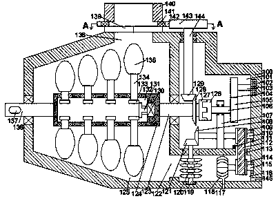
[0013] like Figure 1-Figure 2 As shown, a steam turbine complete set of equipment of the present invention includes a fuselage 100 and a first cavity 101 arranged in the fuselage 100, and a A steam outlet chamber 116, a transmission channel 113 is provided between the first cavity 101 and the steam outlet chamber 116, and a working chamber 125 located at the left end of the first cavity 101 is provided in the fuselage 100, The working chamber 125 communicates with the steam outlet chamber 116 and is provided with an exhaust passage 122. The inner wall of the left end of the first cavity is rotatably connected with a first transmission shaft 123 extending left and right. The first transmission shaft 123 The left end is fixedly connected with the impeller box 124 located in the working chamber 125, the first transmission shaft 123 is provided with a first bevel gear 128 located in the first cavity 101, and the first transmission shaft 123 There is a first meshing plate 127 loc...


PUM


Abstract

The invention discloses complete equipment of a turbine. The complete equipment comprises a machine body and a first cavity formed in the machine body, wherein a steam outlet cavity which is positioned at the lower end of the first cavity is formed in the machine body; a conveying channel is formed between the first cavity and the steam outlet cavity in a communication manner; a working cavity which is positioned at the left end of the first cavity is formed in the machine body; a steam exhaust channel is formed between the working cavity and the steam outlet cavity in a communication manner;a first transmission shaft which extends left and right is connected to the inner wall of the left end of the first cavity through rotation fit; an impeller box which is positioned in the working cavity is fixedly connected to the tail end of the left end of the first transmission shaft; and a first bevel gear which is positioned in the first cavity is arranged on the first transmission shaft. According to the complete equipment, the structure is simple, operation is convenient, the stress area of impellers and wind is changed, working efficiency is improved, a release device is driven to protect the equipment at the first time through exhaust of gases.

Description

technical field [0001] The invention relates to the technical field of energy and power, in particular to a complete set of steam turbine equipment. Background technique [0002] Steam turbine is the most widely used machine in power conversion equipment at the present stage, and its complete set of equipment consists of air intake device, turning device, cylinder and so on. The cranking device in the existing steam turbine is generally manually monitored or monitored by the computer, and there is a certain delay. If it cannot be disengaged in time when the output shaft is running at high speed, it will cause irreversible damage to the cranking motor and increase maintenance costs. At the same time, the angle of the impeller of the traditional steam turbine is fixed, and it is very inconvenient to replace the impeller group as a whole when the work efficiency needs to be changed. Therefore a kind of barring device that breaks away automatically in real time becomes the writ...

Claims


Application Information

Patent Timeline
Patent Type & Authority Applications(China)
IPC IPC(8): F01D15/00F01D15/12F01D25/00
CPCF01D15/00F01D15/12F01D25/00
Inventor 余连平
Owner 余连平
Why Eureka
Try Eureka