
Terminal

A terminal and a technology within the terminal, applied in the field of communication, can solve the problem of taking up a lot of space and achieve the effect of saving space

Active Publication Date: 2019-02-01
VIVO MOBILE COMM CO LTD
View PDF8 Cites 2 Cited by
  • Summary
  • Abstract
  • Description
  • Claims
  • Application Information

AI Technical Summary

Problems solved by technology

[0004] The embodiment of the present invention provides a terminal to solve the technical problem that the antenna setting scheme in the existing terminal occupies a large space

Method used


Image

  • Terminal
  • Terminal
  • Terminal

Examples


Embodiment Construction

[0016] The following will clearly and completely describe the technical solutions in the embodiments of the present invention with reference to the accompanying drawings in the embodiments of the present invention. Obviously, the described embodiments are some of the embodiments of the present invention, but not all of them. Based on the embodiments of the present invention, all other embodiments obtained by persons of ordinary skill in the art without creative efforts fall within the protection scope of the present invention.

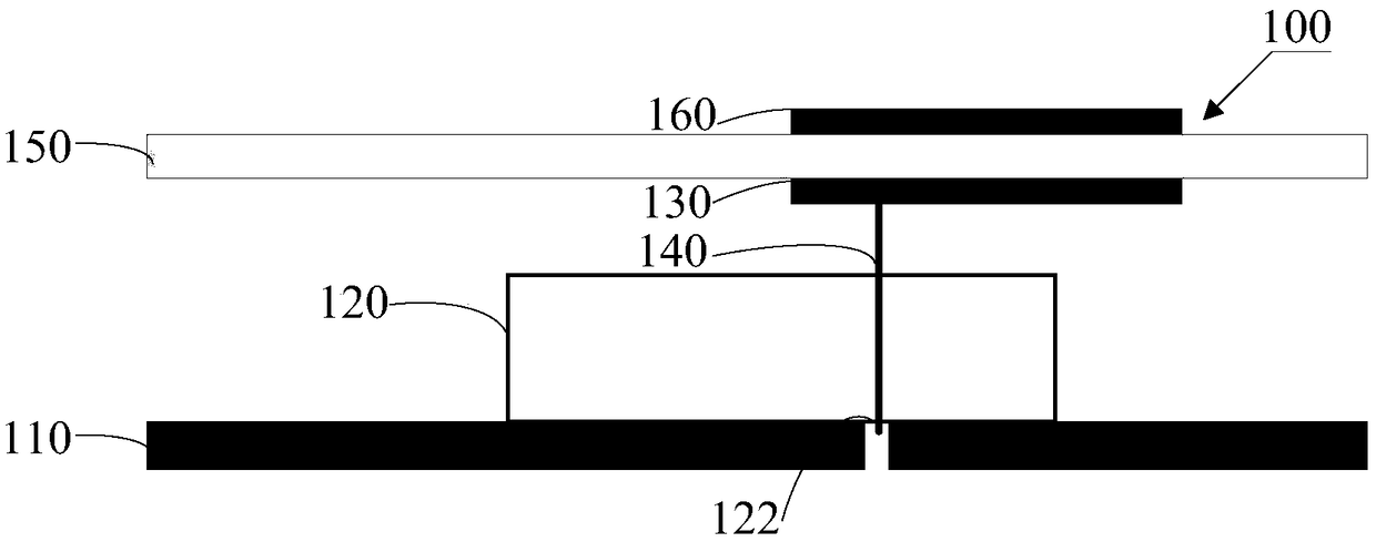
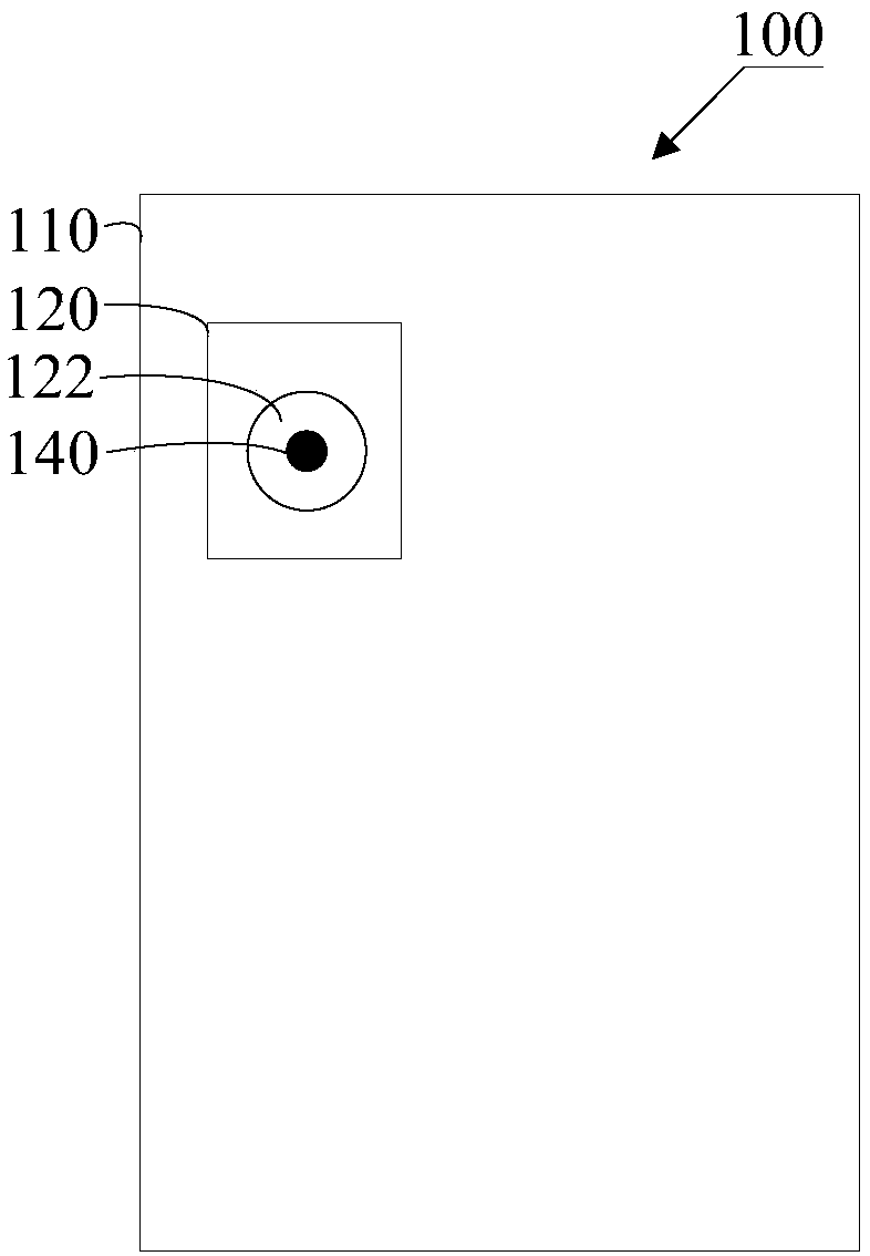
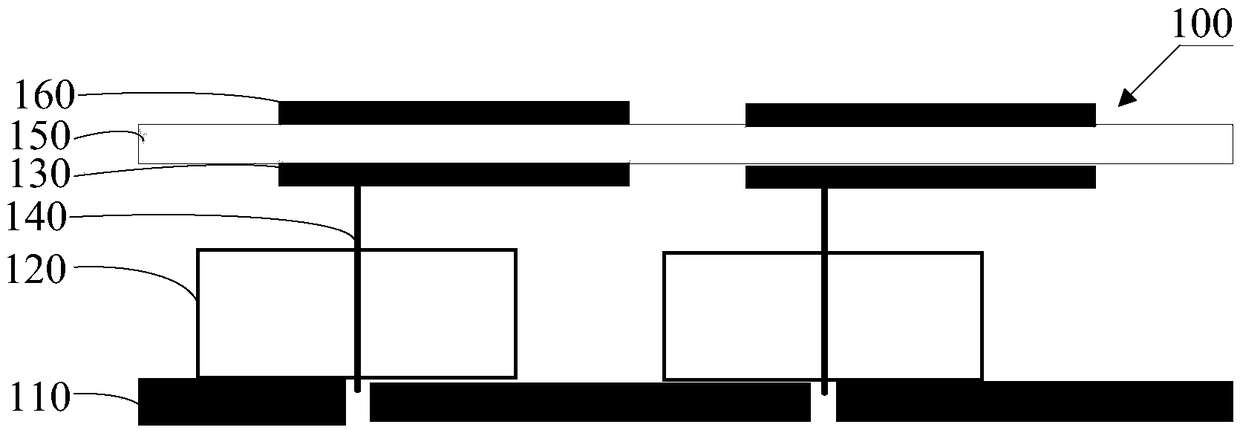
[0017] see figure 1 with figure 2 , is a schematic structural diagram of a terminal provided by an embodiment of the present invention. Such as figure 1 with figure 2 As shown, a terminal 100, the terminal 100 is provided with a grounding plate 110 and a shielding case 120, the shielding case 120 is electrically connected to the grounding plate 110, and the shielding case 120 is provided with a radio frequency circuit board 121, The terminal 100 ...


PUM


Abstract

The present invention provides a terminal. The terminal is internally provided with a grounding plate and a shielding cover, the shielding cover is electrically connected with the grounding plate, theshielding cover is internally provided with a radio frequency circuit board, the terminal is internally provided with a first radiation piece arranged at intervals with the shielding cover, the terminal is further internally provided with a signal transmission line connected with the first radiation piece and the radio frequency circuit board; the radio frequency circuit board, the signal transmission line and the first radiation piece commonly form an antenna unit of the terminal. According to the embodiment of the invention, the original shielding cover and the grounding plate in the terminal are employed, and the radio frequency circuit board in the shielding cover is connected with the first radiation piece arranged at intervals with the shielding cover through the signal transmissionline. Therefore, the radio frequency circuit board, the signal transmission line and the first radiation piece can form the antenna unit of the terminal. The terminal provided by the embodiment of the invention does not need extra distribution of a space to arrange an antenna unit so as to save the space occupation in the terminal.

Description

technical field [0001] The present invention relates to the technical field of communications, and in particular to a terminal. Background technique [0002] In order to optimize the communication function of the terminal, an antenna needs to be added in the terminal. At present, when an antenna is added in a terminal, the complete antenna device is generally installed at the head end or tail end of the terminal, close to the surrounding area of ​​the existing communication antenna, or occupies the installation area of ​​the camera, earphone and other accessories in the terminal. As a result, the arrangement of the antenna needs to occupy a relatively large space. [0003] It can be seen that there is a technical problem of occupying a large space in the existing arrangement scheme of the antenna in the terminal. Contents of the invention [0004] An embodiment of the present invention provides a terminal, so as to solve the technical problem that the arrangement scheme ...

Claims


Application Information

Patent Timeline
Patent Type & Authority Applications(China)
IPC IPC(8): H01Q1/22H01Q1/24H01Q1/38H01Q1/48H01Q1/50H01Q1/52H01Q21/00H01Q23/00
CPCH01Q1/22H01Q1/2258H01Q1/242H01Q1/38H01Q1/48H01Q1/50H01Q1/526H01Q21/00H01Q23/00
Inventor 王义金简宪静
Owner VIVO MOBILE COMM CO LTD
Learn More