
Cable connector device

A technology of plug joints and cables, which is applied to two-part connection devices, parts of connection devices, coupling devices, etc., can solve problems such as power outages in 35kV power supply areas, low power supply reliability, and many electrical equipment, so as to reduce power outage time, Prevent electric field concentration and partial discharge, easy installation and matching effect

Pending Publication Date: 2019-02-01
HONGHE POWER SUPPLY BUREAU OF YUNNAN POWER GRID
View PDF6 Cites 4 Cited by
  • Summary
  • Abstract
  • Description
  • Claims
  • Application Information

AI Technical Summary

Problems solved by technology

For substations with a voltage level of 110kV and above, the 35kV outgoing line is often the main power supply for important users or the next-level power grid. Therefore, a power outage or emergency power outage caused by a fault in the 35kV electrical equipment in the substation will cause a large area of ​​the 35kV power supply area Power failure, resulting in low power supply reliability
[0003] The 35kV equipment in the substation is limited by the area, and there are many electrical equipment, small intervals, compact equipment installation, and complicated wiring. As a result, such equipment in the substation can only be repaired or eliminated by power outages, which also causes important users, and even There was a power outage at the next substation

Method used


Image

  • Cable connector device
  • Cable connector device
  • Cable connector device

Examples


Embodiment Construction

[0045] The following will clearly and completely describe the technical solutions in the embodiments of the present invention with reference to the drawings in the embodiments of the present invention. Apparently, the described embodiments are only some of the embodiments of the present invention, but not all of them. Based on the embodiments of the present invention, all other embodiments obtained by persons of ordinary skill in the art without creative efforts fall within the protection scope of the present invention.

[0046] Reference herein to "one embodiment" or "an embodiment" refers to a particular feature, structure or characteristic that can be included in at least one implementation of the present invention. In the description of the present invention, it should be understood that the orientation or positional relationship indicated by the terms "upper", "lower", "top", "bottom" etc. is based on the orientation or positional relationship shown in the drawings, and i...


PUM


Abstract

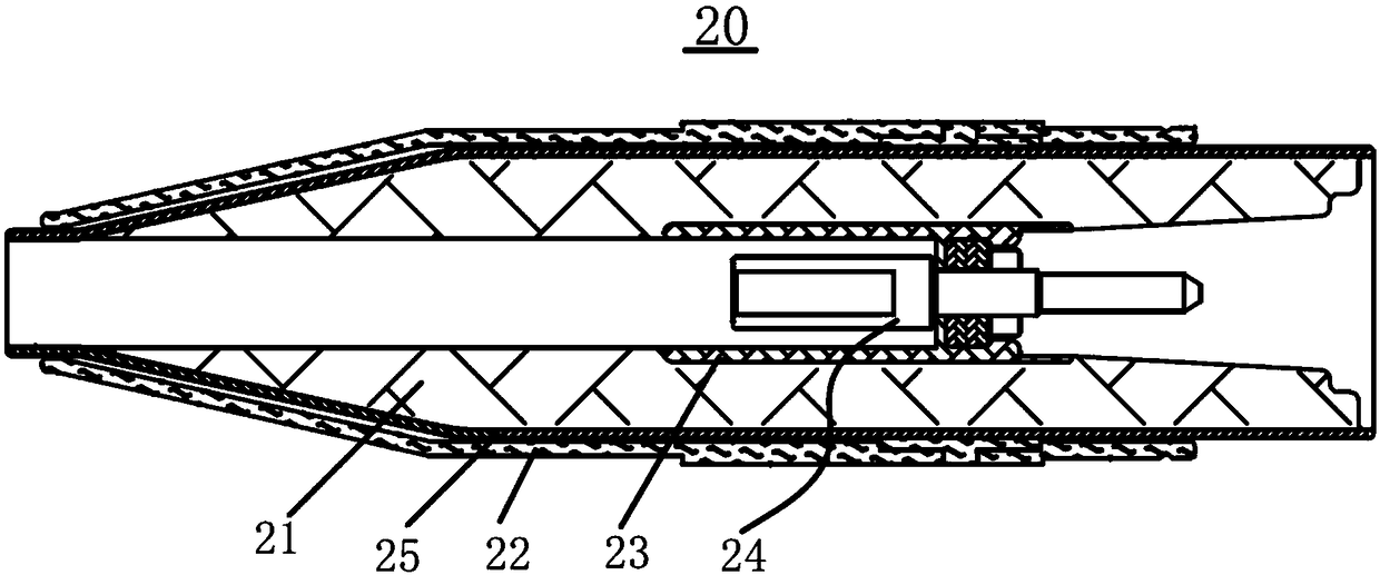
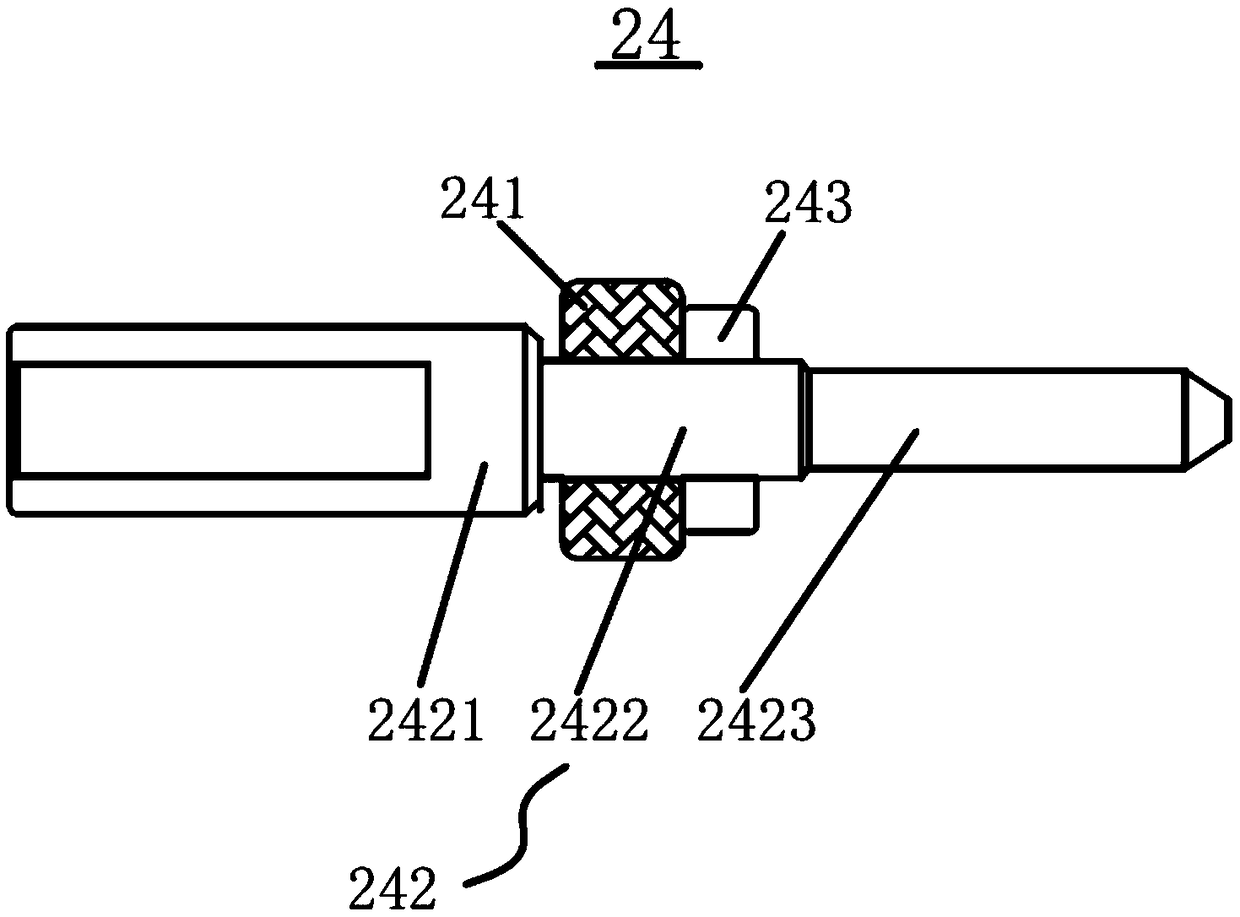
The invention provides a cable connector device, and the device comprises a central connector and two terminal connectors. Two ends of the central connector are correspondingly connected with the twoterminal connectors in a detachable manner. The central connector comprises a connector, two connection sleeves, and two self-locking mechanisms. Two ends of the connector are respectively connected with the two connection sleeves, and the two self-locking mechanisms are respectively disposed on the two connection sleeves, and are used for locking and unlocking the two central connectors. Each terminal connector comprises an insulating part and a terminal housing, wherein the terminal housing is disposed outside the insulating part, and the insulating part is provided with a plugging connection terminal. There is the first distance between each terminal housing and the corresponding plugging connection terminal, and the outer wall, close to one side of the corresponding plugging connectionterminal, of each terminal housing is provided with at least one positioning groove cooperating with the corresponding self-locking mechanism. According to the invention, the device can achieve the quick locking and separation of the central connector and the terminal connectors through the self-locking mechanisms, and improves the cable connection efficiency.

Description

technical field [0001] The invention relates to the technical field of cable accessories, in particular to a cable plug joint device. Background technique [0002] The 35kV power grid of the substation is the main grid structure of the county-level power supply enterprises, and the surrounding users are radiated through the 35kV substation for power supply. For substations with a voltage level of 110kV and above, the 35kV outgoing line is often the main power supply for important users or the next-level power grid. Therefore, a fault in the 35kV electrical equipment in the substation causes a power outage or emergency power outage for repairs, which will cause a large area of ​​the 35kV power supply area Power outages lead to low power supply reliability. [0003] The 35kV equipment in the substation is limited by the area, and there are many electrical equipment, small intervals, compact equipment installation, and complicated wiring. As a result, such equipment in the sub...

Claims


Application Information

Patent Timeline
Patent Type & Authority Applications(China)
IPC IPC(8): H01R13/502H01R13/627H01R13/629H01R13/6591H01R24/38
CPCH01R13/502H01R13/627H01R13/629H01R13/6591H01R24/38
Inventor 刘宇崔玉坤曹安全
Owner HONGHE POWER SUPPLY BUREAU OF YUNNAN POWER GRID
Learn More