Automatic grouting forming device for ceramic blanks

A technology for automatic grouting and ceramic body, which is applied in the direction of ceramic molding machines, supply devices, manufacturing tools, etc., can solve the problems of uneven thickness of the body, low production efficiency, and inability to standardize production, and achieve low production costs, The effect of high production efficiency and simple structure

Pending Publication Date: 2019-02-05
德化富安陶瓷科技有限公司
View PDF0 Cites 0 Cited by
  • Summary
  • Abstract
  • Description
  • Claims
  • Application Information

AI Technical Summary

Problems solved by technology

[0003] The invention provides an automatic grouting molding device for ceramic bodies to overcome the existing problems of non-stan

Method used


Image

  • Automatic grouting forming device for ceramic blanks
  • Automatic grouting forming device for ceramic blanks
  • Automatic grouting forming device for ceramic blanks

Examples


Embodiment approach 1

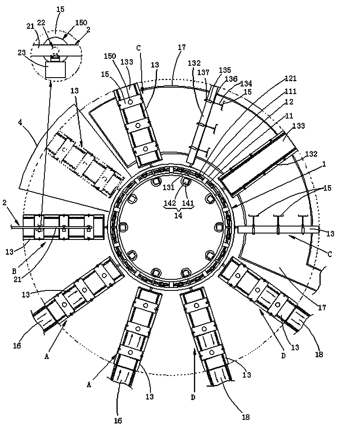
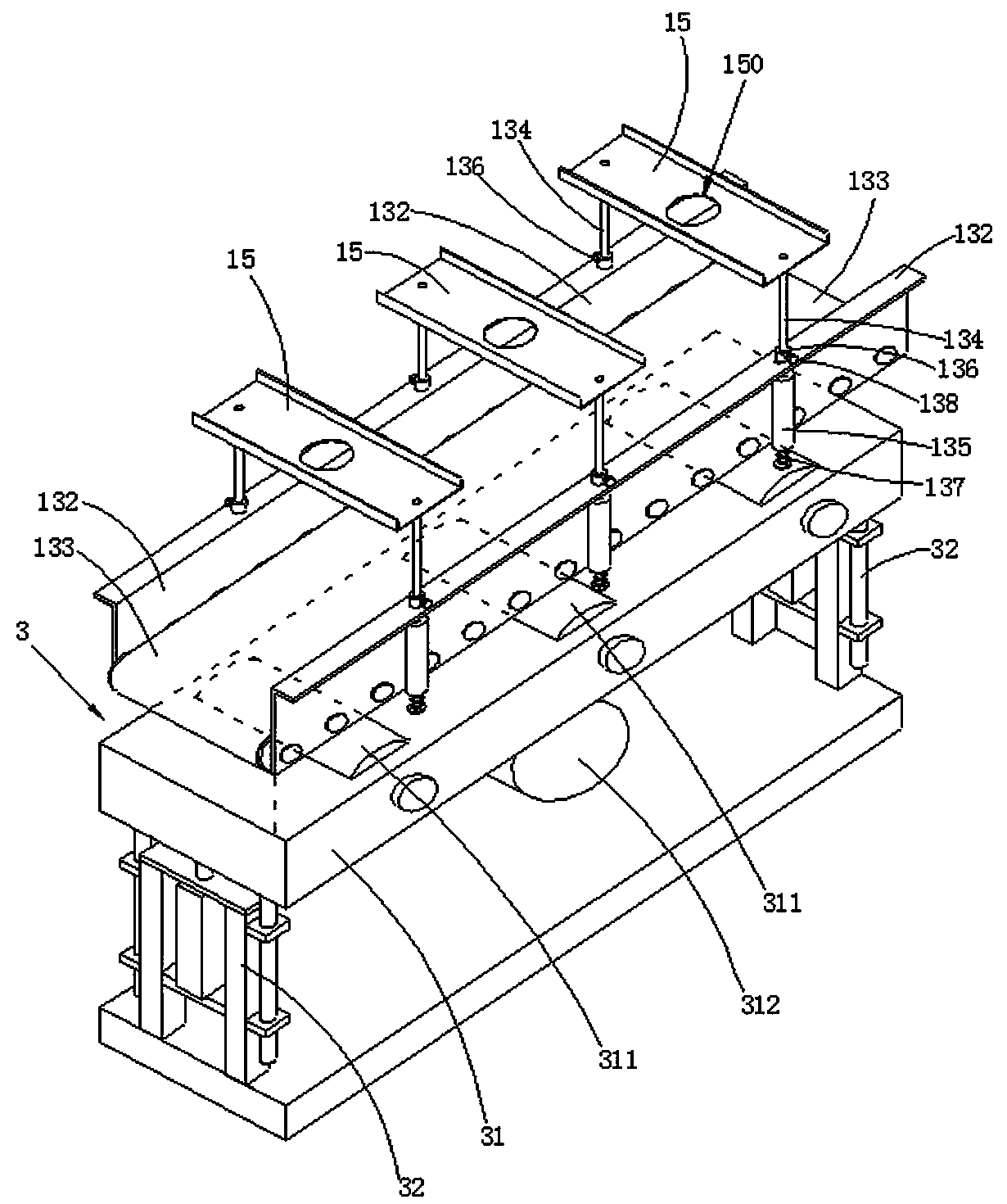
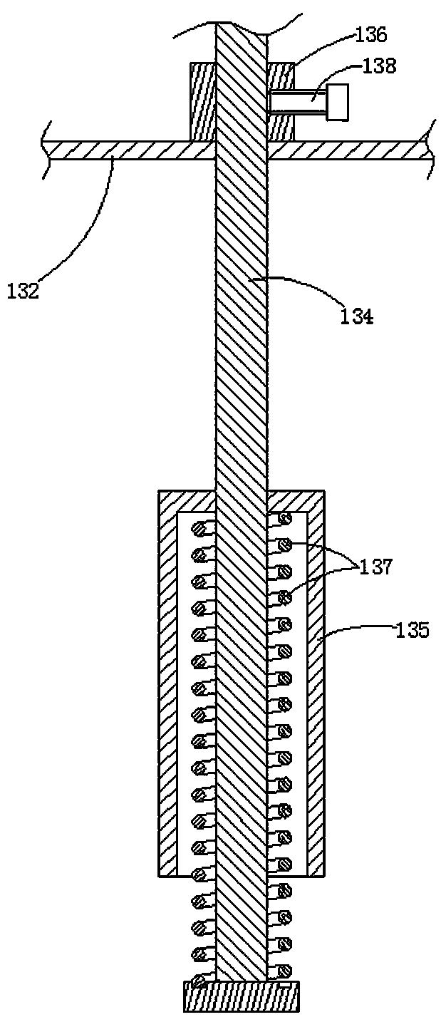
[0025] refer to figure 1 , figure 2 , image 3 , This embodiment relates to an automatic grouting molding device for a ceramic body, including a main frame 1 and an upper mold station A, a grouting station B, a pouring station C and a mold ejection station arranged on the main frame 1 D; the above-mentioned main frame 1 includes a base 11 and a rotating frame 12, and the rotating frame 12 is assembled on the base 11 for fixed-axis rotation; the top surface of the above-mentioned base 11 is provided with a circular guide rail 111, and the above-mentioned rotating The bottom of the frame 12 is equipped with several pulleys 121, and the pulleys 121 slide directionally along the guide rail 111, and the base 11 is equipped with a hydraulic motor that drives the rotating frame 12 to rotate. The peripheral surface of the rotating frame 12 is provided with ten mold-carrying tables 13 for placing moulds. The mold-carrying tables 13 are mounted on the rotating frame 12 through a driv...

Embodiment approach 2

[0031] The difference between the automatic grouting molding device for ceramic body in this embodiment and the automatic grouting molding device in Embodiment 1 is that: refer to Figure 4 , Figure 5 , the driving mechanism 14 adopted in this embodiment is a simple way with low cost. The driving mechanism 14 of this embodiment includes a driving wheel 143, a limit wheel 144 and a guide rail 145, and the driving wheel 143 is fixedly assembled on the above-mentioned driving shaft 131 , the limit wheel 144 is coaxially assembled on the eccentric position of the drive wheel 143, and the guide rail 145 is fixedly assembled on the above-mentioned main frame 1, and the guide rail 145 is preferably two upper and lower parallel arrangements. The limit wheel 144 Then it is assembled between two guide rails 145, and the limit wheel 144 slides along with the extension of the guide rails 145; the guide rail 145 of the pouring station C has at least one peak section 146 and at least one w...


PUM


Abstract

The invention relates to an automatic grouting forming device for ceramic blanks. The automatic grouting forming device comprises a main rack and further comprises a die feeding station, a grouting station, a grout pouring station and a die discharging station, all of which are arranged on the main rack. The main rack comprises a base and a rotation frame, and the rotation frame does the fixed-axis rotation action to be assembled to the base. A plurality of die carrying tables for carrying dies are arranged on the circumferential face of the rotation frame and assembled to the rotation frame in a drive shaft fixed-axis rotation manner. The rotation frame is provided with drive mechanisms for driving drive shafts to rotate, and the die carrying tables are provided with die pressing plates for pressing and limiting the dies. The dies are assembled to the die carrying tables through the die feeding station, grouting is conducted on the dies on the die carrying tables at the grouting station, surplus grout in the dies is poured out at the grout pouring station, and the dies carrying blanks are unloaded from the die discharging station. The forming device can automatically and intelligently finish the procedures of die feeding, grouting, grout pouring and die discharging, more standard ceramic blanks can be obtained, and the production efficiency is high.

Description

technical field [0001] The invention relates to the field of preparation of a ceramic body, in particular to an automatic grouting molding device for a ceramic body. Background technique [0002] At present, the preparation of the ceramic green body is mostly by injecting slurry into a plaster mold with a required cavity, and after the gypsum mold absorbs the moisture of the slurry in contact with it to make it solidify, the excess slurry is exported, so that the The inner wall of the cavity forms the required green body, and the green body is completely solidified before being demoulded and taken out. The existing grouting process is mostly realized by manual operation. However, when manual mass production is carried out, it is difficult to perform timely grouting treatment according to the grouting sequence, and the timing of grouting is only controlled by manual experience, resulting in the green body produced The thickness is not uniform, the production cannot be standa...

Claims


Application Information

Patent Timeline
IPC IPC(8): B28B13/02B28B3/00
CPCB28B3/00B28B13/02
Inventor 陈少志
Owner 德化富安陶瓷科技有限公司
Why Eureka
Try Eureka