
Slide bar assembly structure

A component structure and sliding rod technology, applied in the direction of slender components, building components, etc., can solve the problems of inconvenient use, insufficient structural strength, complex structure of sliding rods, etc., and achieve the effect of simple structure and convenient use

Inactive Publication Date: 2019-02-05
胡龙春
View PDF0 Cites 0 Cited by
  • Summary
  • Abstract
  • Description
  • Claims
  • Application Information

AI Technical Summary

Problems solved by technology

[0002] The existing sliding rods have the disadvantages of complex structure, inconvenient use, and insufficient structural strength.

Method used


Image

  • Slide bar assembly structure

Examples


Embodiment Construction

[0007] Below in conjunction with accompanying drawing and specific embodiment, further illustrate the present invention, should be understood that these examples are only for illustrating the present invention and are not intended to limit the scope of the present invention, after having read the present invention, those skilled in the art will understand various aspects of the present invention All modifications of the valence form fall within the scope defined by the appended claims of the present application.

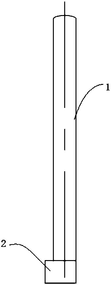
[0008] refer to figure 1 The structure of a slide bar assembly shown includes a slide bar body 1 and a stopper 2 arranged at the lower end of the slide bar body 1 , one end of the stopper 2 and one end of the slide bar body 1 are located at the same vertical On the surface, the horizontal width of the limiting block 2 is greater than that of the slide bar main body 1, and the slide bar main body 1 is provided with several vertical grooves, and the upper end of the sl...


PUM


Abstract

The invention discloses a slide bar assembly structure. The slide bar assembly structure comprises a slide bar body and a limiting block which is arranged at the lower end of the slide bar body. One end of the limiting block and one end of the slide bar body are located on the same vertical plane. The horizontal width of the limiting block is larger than that of the slide bar body. The slide bar body is provided with a plurality of vertical grooves, and the upper end of the slide bar body is of a cambered surface structure.

Description

technical field [0001] The invention relates to a sliding bar assembly structure. Background technique [0002] The existing slide bar has the disadvantages of complex structure, inconvenient use, insufficient structural strength and the like. Contents of the invention [0003] Purpose of the invention: In order to solve the deficiencies in the prior art, the present invention proposes a sliding bar assembly structure. [0004] Technical solution: In order to achieve the above purpose, the technical solution adopted by the present invention is: a slide bar assembly structure, including a slide bar body and a limit block arranged at the lower end of the slide bar body, one end of the limit block is connected to the slide bar One end of the rod main body is located on the same vertical plane, the horizontal width of the limiting block is larger than that of the sliding rod main body, and several vertical grooves are arranged on the sliding rod main body, and the upper end o...

Claims


Application Information

Patent Timeline
Patent Type & Authority Applications(China)
IPC IPC(8): F16S3/00
CPCF16S3/00
Inventor 胡龙春
Owner 胡龙春
Learn More