Backlight source guide plate with lattice point

A technology of backlight and light guide plate, which is applied in the field of light guide plate, can solve the problems of poor positioning of light guide plate and light effect, inability to enhance and diffuse light, and inability to effectively use light, etc., to achieve good light guide effect, simple structure and low cost low effect

Active Publication Date: 2019-02-05
YANCHENG SANDING ELECTRONICS TECH CO LTD
View PDF7 Cites 0 Cited by
  • Summary
  • Abstract
  • Description
  • Claims
  • Application Information

AI Technical Summary

Problems solved by technology

[0002] The positioning and light effect of the traditional backlight light guide plate are not good, and the structural requirements and effect requirements of the backlight in the market will become higher and higher. With the rapid development of backlight technology, the overall luminous effect and performance requirements of the backlight will be higher and higher
[0003] Most of the existing backlight light guide plates cannot effectively use the light, nor can they enhance and diffuse the light, and the light guide effect is not good.

Method used


Image

  • Backlight source guide plate with lattice point
  • Backlight source guide plate with lattice point
  • Backlight source guide plate with lattice point

Examples


Embodiment

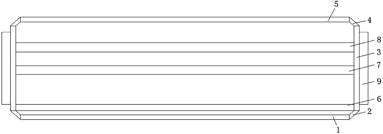
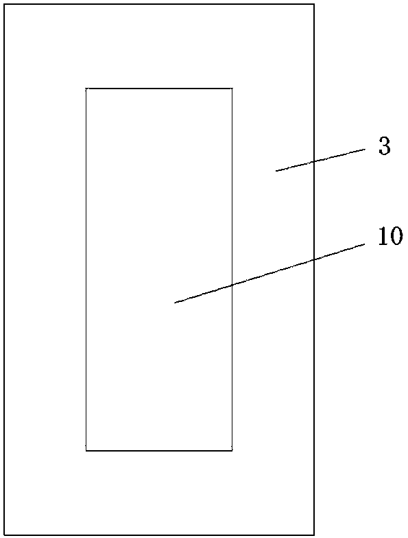
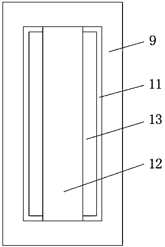
[0019] refer to Figure 1-4 , the present embodiment proposes a backlight light guide plate with network dots, including a light incident plate 1 and a light output plate 5, the light incident plate 1 and the light output plate 5 are arranged in parallel, and both sides of the light incident plate 1 and the light output plate 5 are provided with vertical The side reflector 3 provided, the side reflector 3 is provided with a first oblique reflector 2 near the light incident plate 1, the side reflector 3 is provided with a second oblique reflector 4 near the light exit plate 5, and the light incident plate 1. The first inclined reflector 2, the side reflector 3, the second inclined reflector 4 and the light-emitting plate 5 are of an integrated structure, in which a single A surface reflector 6, a diffusion plate 8 is arranged between the inner walls of the two side reflectors 3 close to the side of the light-emitting plate 5, and a brightening plate 7 is also provided between t...


PUM


Abstract

The invention discloses a backlight source guide plate with a lattice point. The backlight source guide plate comprises an incident plate and a light giving-out plate, wherein the incident plate and the light giving-out plate are arranged in parallel, side reflection plates are arranged at two sides of the incident plate and the light giving-out plate and are vertically arranged, a first oblique reflection plate is arranged at one side, near to the incident plate, of each side reflection plate, a second oblique reflection plate is arranged at one side, near to the light giving-out plate, of the side reflection plate, the incident plate, the first oblique reflection plate, the side reflection plate, the second oblique reflection plate and the light giving-out plate are of an integrated structure, a single-surface reflection plate is fixedly arranged between inner walls of sides, near to the incident plate, of the two side reflection plates, a diffusion plate is arranged between inner walls of sides, near to the light giving-out plate, of the two side reflection plates, a brightening plate is further arranged between the single-surface reflection plate and the diffusion plate, the single-surface reflection plate, the brightening plate and the diffusion plate are arranged in parallel, and connection blocks are arranged at two sides of the brightening plate and the diffusion plate.The backlight source guide plate has a favorable light guide effect and is convenient to use, and angle adjustment of a light ray is facilitated.

Description

technical field [0001] The invention relates to the technical field of light guide plates, in particular to a backlight light guide plate with dots. Background technique [0002] The positioning and light effect of the traditional backlight light guide plate are not good, and the structural requirements and effect requirements of the backlight in the market will become higher and higher. With the rapid development of backlight technology, the overall luminous effect and performance requirements of the backlight will be higher and higher. [0003] Most of the existing backlight light guide plates cannot effectively utilize the light, nor can they enhance and diffuse the light, and the light guiding effect is not good. Contents of the invention [0004] Based on the technical problems existing in the background technology, the present invention proposes a backlight light guide plate with dots. [0005] A backlight light guide plate with dots proposed by the present inventi...

Claims


Application Information

Patent Timeline
Patent Type & Authority Applications(China)
IPC IPC(8): G02B6/00
CPCG02B6/0031G02B6/0051G02B6/0055
Inventor 赵圣铭
Owner YANCHENG SANDING ELECTRONICS TECH CO LTD
Why Eureka
Try Eureka