
Optical power measurement device

A measurement device and optical power technology, applied in transmission monitoring/testing/fault measurement systems, etc., to achieve the effect of reducing operation steps, improving work efficiency, and reducing uncertain loss

Active Publication Date: 2019-02-05
STATE GRID CORP OF CHINA +1
View PDF6 Cites 4 Cited by
  • Summary
  • Abstract
  • Description
  • Claims
  • Application Information

AI Technical Summary

Problems solved by technology

[0004] In view of this, the embodiment of the present invention provides an optical power measurement device to solve the problem that the optical power meter in the prior art only has an FC type optical interface, which causes the , the problem of not being able to directly use the instrument for optical power measurement

Method used


Image

  • Optical power measurement device
  • Optical power measurement device

Examples


Embodiment Construction

[0019] In the following description, specific details such as specific system structures and technologies are presented for the purpose of illustration rather than limitation, so as to thoroughly understand the embodiments of the present invention. It will be apparent, however, to one skilled in the art that the invention may be practiced in other embodiments without these specific details. In other instances, detailed descriptions of well-known systems, devices, circuits, and methods are omitted so as not to obscure the description of the present invention with unnecessary detail.

[0020] In order to illustrate the technical solutions of the present invention, specific examples are used below to illustrate.

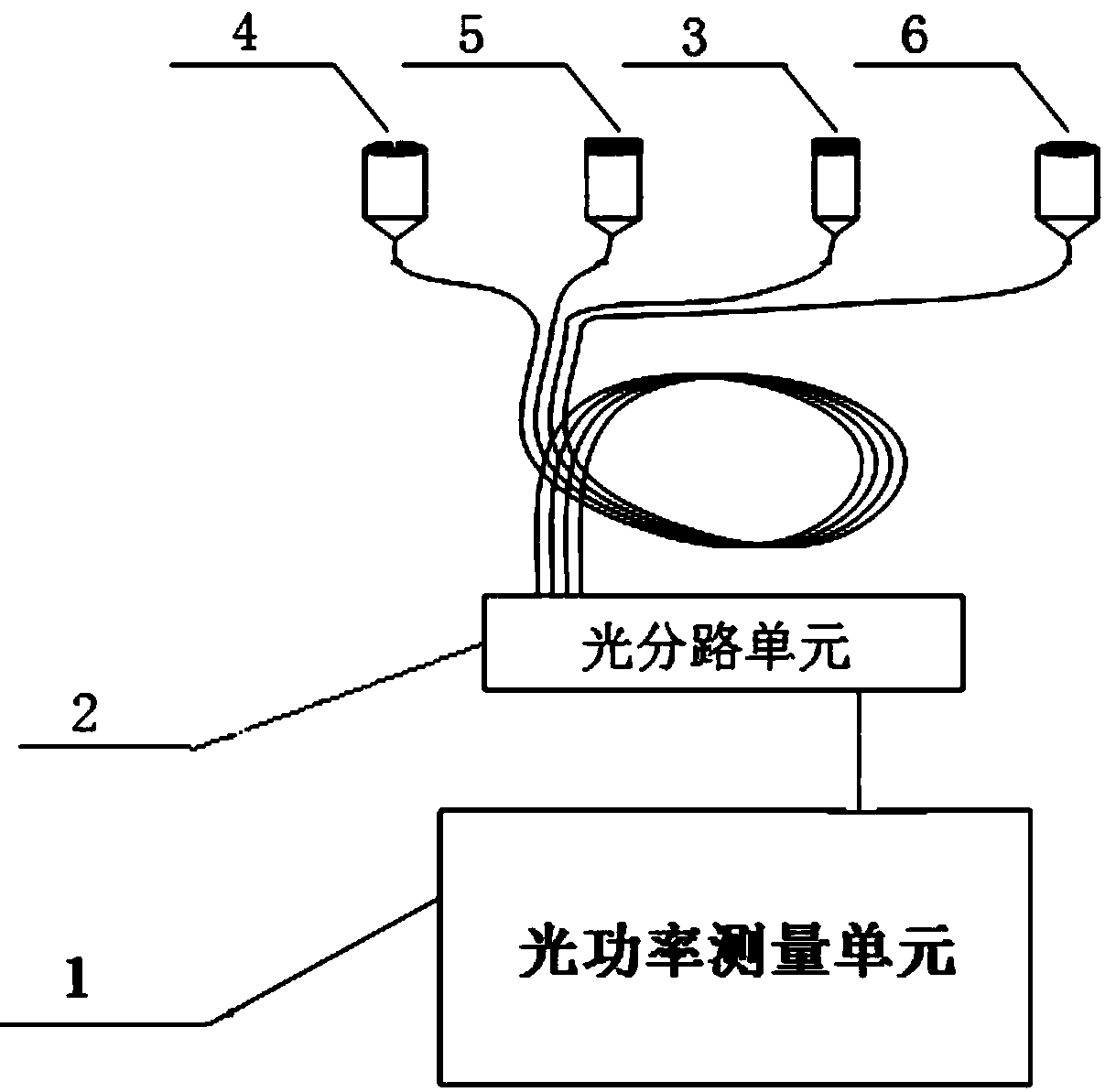
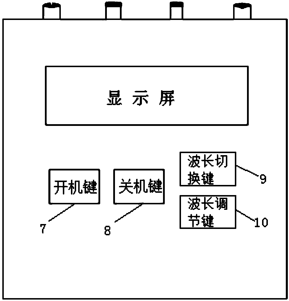
[0021] Such as figure 1 As shown, an optical power measuring device provided by the embodiment of the present invention includes: an optical power measuring unit 1, an optical splitting unit 2 and an interface, and the interface includes an LC type externally connected...


PUM


Abstract

The invention is applicable to the technical field of optical power measurement, and provides an optical power measurement device. The device comprises an optical power measurement unit, an optical splitting unit and an interface, wherein the interface comprises an LC interface of external Huawei SDH transmission equipment and ZTE OTN transmission equipment, an FC interface of external NEC SDH transmission equipment, an SC interface of external ECI SDH transmission equipment and an ST interface of external relay protection transmission equipment; the LC interface, the FC interface, the SC interface and the ST interface are all connected with the optical splitting unit; the optical splitting unit is connected with the optical power measurement unit; and the power measurement value of optical power measurement device is the sum of the test value of the optical power measurement unit and the loss value of the optical splitting unit. Through adoption of the above scheme, the FC, LC, SC andST interfaces can be measured directly, thereby improving the convenience of work, reducing the uncertain loss of a movable joint of tail fiber, and improving the accuracy of the optical power value.

Description

technical field [0001] The invention belongs to the technical field of optical power measurement, and in particular relates to an optical power measurement device. Background technique [0002] At present, in the field of power system communication transmission, in order to match the optical interface types of mainstream optical transmission equipment, the commonly used pigtail connector models include LC pigtail connectors, which are mostly used in Huawei SDH transmission equipment and ZTE OTN transmission equipment, FC pigtail connectors are mostly used for NEC SDH transmission equipment, SC pigtail connectors are mostly used for ECI SDH transmission equipment, and ST type pigtail connectors are mostly used for relay protection transmission protection equipment. [0003] However, the optical power meter used in actual work has only FC type optical interface, so when working at the optical connector of LC, SC or ST type pigtail connector, it is impossible to directly use th...

Claims


Application Information

Patent Timeline
Patent Type & Authority Applications(China)
IPC IPC(8): H04B10/07
CPCH04B10/07
Inventor 梁雪峰祁利刚黄振段志勇胡伟涛李志伟王亚强付炜平
Owner STATE GRID CORP OF CHINA
Learn More