
Broadcasting sound mounting frame

A mounting frame and sound technology, which is applied to the transducer shell/cabinet/support and other directions, can solve the problems of the weak connection between the hoop and the pole, the troublesome installation process of the mounting frame, and the lack of shock absorption of the mounting frame. Lightweight, long service life and robust construction

Pending Publication Date: 2019-02-05
江苏沃达视听科技有限公司
View PDF1 Cites 1 Cited by
  • Summary
  • Abstract
  • Description
  • Claims
  • Application Information

AI Technical Summary

Problems solved by technology

[0003] The prior art discloses the application number: 201410149828.3 A broadcast audio installation frame, which is used to solve the problems of troublesome installation process and unstable installation of the existing installation frame. The hoop is fixed on the pole, and the other end is installed with a broadcast speaker through a support frame, and also includes a movable installation plate, the fixed end of which is hinged on the side of the fixed bracket through a pin shaft, and at least one The limit portion of the movable end of the movable mounting plate is accommodated. The distance between the limit portion and the pin shaft is less than the length of the movable mounting plate. The movable end of the movable mounting plate can be matched with the mounting groove on the receiving terminal shell. The mounting bracket To avoid complex bundling of the receiving terminal, the hinged fixed mounting plate can enable the installer to simply fix the receiving terminal at high altitude to ensure the safe use of the broadcast audio, but the mounting frame does not have the effect of shock absorption, and the broadcast speaker is working Vibration will be generated when the hoop is fixed, the bolts fixing the hoop are easy to loose, and the connection between the hoop and the pole is not firm, so that the mounting bracket is easy to fall and cause damage to the broadcast speaker

Method used


Image

  • Broadcasting sound mounting frame
  • Broadcasting sound mounting frame
  • Broadcasting sound mounting frame

Examples


Embodiment Construction

[0021] The following will clearly and completely describe the technical solutions in the embodiments of the present invention with reference to the accompanying drawings in the embodiments of the present invention. Obviously, the described embodiments are only some, not all, embodiments of the present invention. Based on the embodiments of the present invention, all other embodiments obtained by persons of ordinary skill in the art without making creative efforts belong to the protection scope of the present invention.

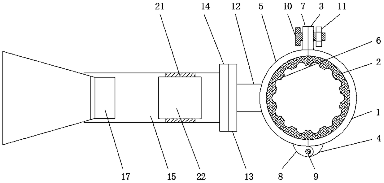
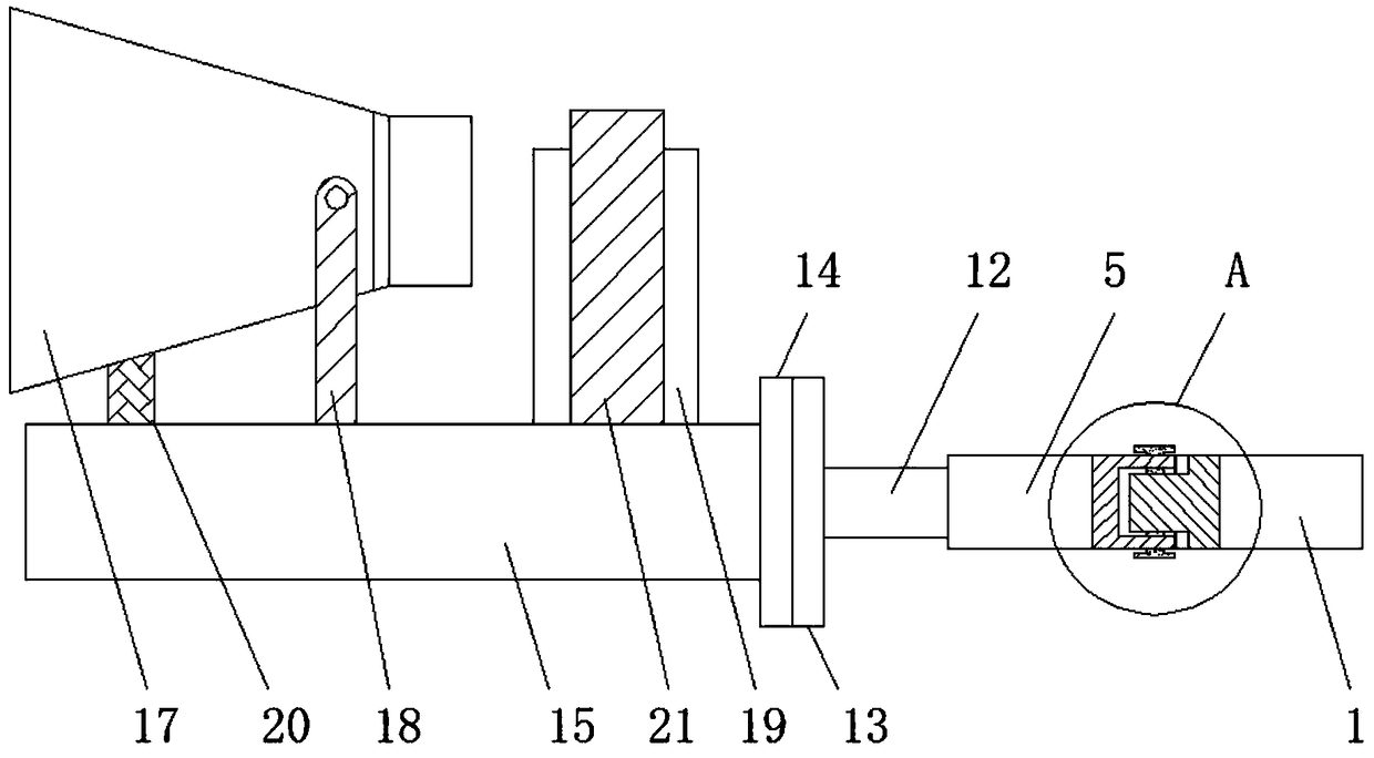
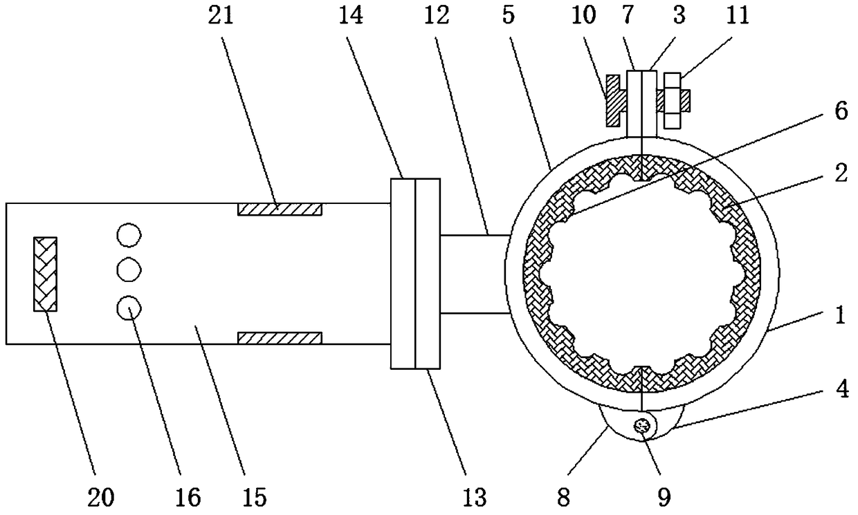
[0022] see Figure 1-4 , an embodiment provided by the present invention: a broadcast audio installation frame, including a first fixing clip 1, the left side surface of the first fixing clip 1 is pasted with a first shockproof pad 2 by strong glue, and the first fixing clip 1 The rear end of the first fixed piece 3 is fixed by welding, and the front end of the first fixed clip 1 is fixedly connected with the first connecting block 4 by welding. The left side ...


PUM


Abstract

The invention discloses a broadcasting sound mounting frame. The broadcasting sound mounting frame comprises a first fixing clamp, wherein the left side surface of the first fixing clamp is pasted with a first shock pad by strong glue; the left side of the first fixing clamp is provided with a second fixing clamp; the right side surface of the second fixing clamp is pasted with a second shock padby strong glue; a connecting rod is fixed to the middle part of the right side surface of the second fixing clamp by welding; a first flange is welded at the right end of the connecting rod; one sideof the first flange far away from the connecting rod is fixedly connected with a second flange by a bolt; a fixed bracket is welded on the right side surface of the second flange; the left part of theupper side surface of the fixed bracket is provided with mounting holes at intervals; a support block is arranged on the left side of the mounting holes; and a broadcasting loudspeaker is arranged above the support block. The broadcasting sound mounting frame is made of a carbon fiber composite material and an aluminum alloy material, so that the mounting frame has the advantages of light weight,firm structure and long service life.

Description

technical field [0001] The invention relates to the technical field of broadcasting audio, in particular to a broadcasting audio installation frame. Background technique [0002] Today, with the rapid development of information technology, the dissemination of information is very important. As one of the most important communication media, broadcast audio equipment can disseminate information, supervise public opinion, provide entertainment, etc. The broadcasting horn is also a kind of broadcasting horn, which is widely used in rural areas. Mounting brackets are required for the installation of broadcast speakers. [0003] The prior art discloses the application number: 201410149828.3 A broadcast audio installation frame, which is used to solve the problems of troublesome installation process and unstable installation of the existing installation frame. The hoop is fixed on the pole, and the other end is installed with a broadcast speaker through a support frame, and also...

Claims


Application Information

Patent Timeline
Patent Type & Authority Applications(China)
IPC IPC(8): H04R1/02
CPCH04R1/02
Inventor 张卓王贺姜云天刘冰
Owner 江苏沃达视听科技有限公司
Learn More