

High trip rate drilling rig
A technology for drilling rigs and pipe fittings, applied in the field of land-based transportable drilling rigs, can solve the problems of difficult loading and unloading, speeding up the tripping rate, increasing risks, etc.
Inactive Publication Date: 2019-02-05
SCHLUMBERGER TECH LTD BV
View PDF7 Cites 2 Cited by
- Summary
- Abstract
- Description
- Claims
- Application Information
AI Technical Summary
Problems solved by technology
Three are longer and therefore more difficult to handle due to their length and weight and the natural wave shape they create when moving
Additionally, accelerating the desired tripping rate increases risk
Method used
View moreImage
Smart ImageViewing Examples

Examples
Embodiment approach
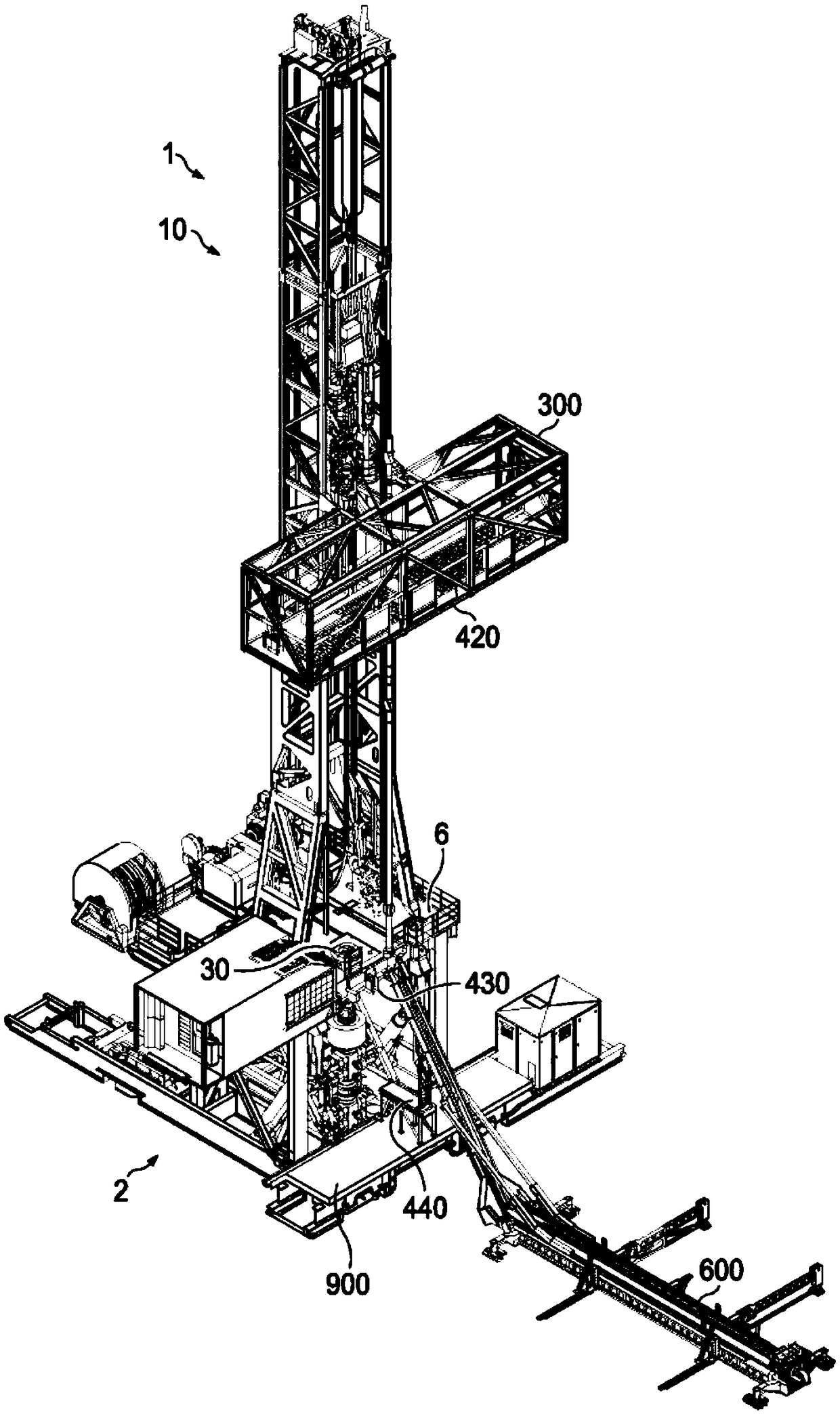
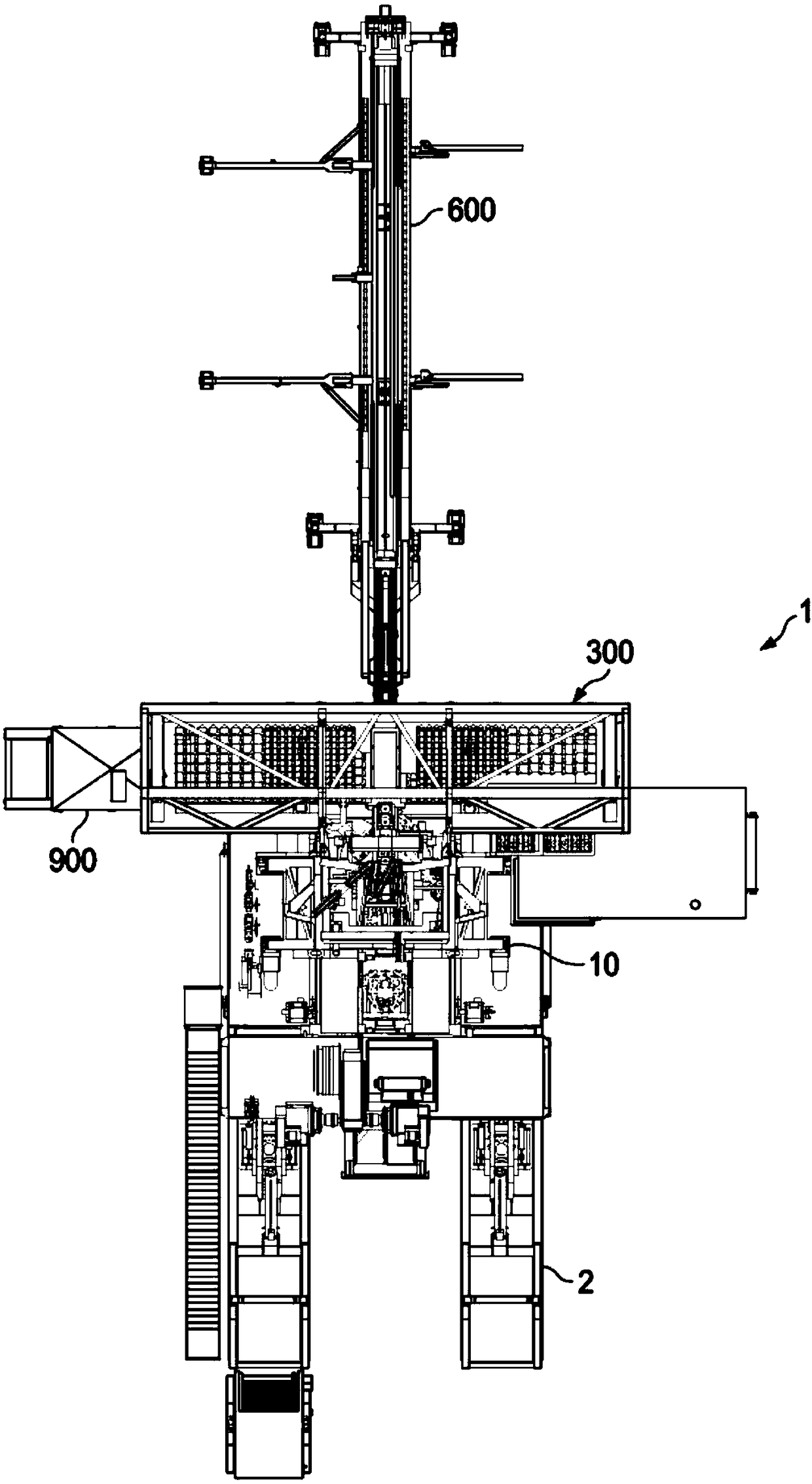
[0163] 1. A drilling rig [1] comprising:
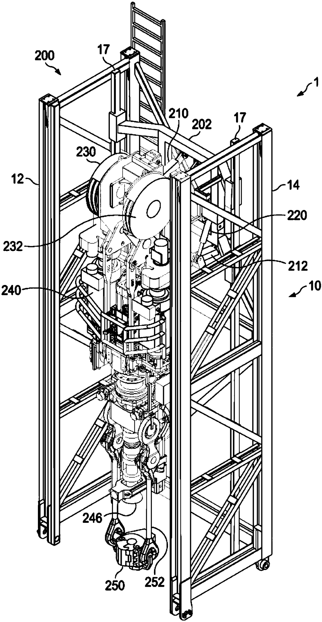
[0164] a top drive assembly [200] that can translate vertically along the mast [10] of the drilling rig [1];
[0165] a tubular delivery arm [500] translatable vertically along said mast [10]; and
[0166] The tubular delivery arm [500] has a tubular clasp [550] movable between a wellhead center position [30] above wellhead center and a second position [50] forward of the wellhead center position .
[0167] 2. The drilling rig according to embodiment 1, further comprising:
Login to View More PUM
 Abstract
A high trip rate drilling rig has first handling equipment to transport stands in / out of setback, second handling equipment to deliver stands to / from well center, and a hand-off position to set down stands for exchange between first / second equipment. Second equipment can include a top drive and a delivery arm translatable along the mast past each other, and a clasp on the arm slidable on the standfor constraint below the upper end, which can allow the top drive to engage / disengage the constrained stand above the arm. A high trip rate method transports stands in / out of setback, delivers standsto / from well center, and sets down and hands off stands at hand-off position between the setback transportation and well center delivery. The delivery can include engaging / dis engaging the top driveand a stand constrained by the clasp.
Description
[0001] Cross References to Related Applications [0002] This document claims the benefit of and priority to the following patent applications: U.S. Provisional Application Serial No. 62 / 330,244, filed May 1, 2016; U.S. Provisional Application Serial No. 62 / 330,012, filed April 29, 2016; April 2016 U.S. Provisional Application Serial No. 62 / 330,016 filed on 29 April; U.S. Provisional Application Serial No. 62 / 330,021 filed on April 29, 2016; U.S. Provisional Application Serial No. 62 / 330,200 filed on May 1, 2016; International Application No. PCT / US2016 / 062402, filed November 17; International Application No. PCT / US2016 / 061956, filed November 15, 2016; and International Application No. PCT / US2016 / 061952, filed November 15, 2016; these Each of the patents is incorporated herein by reference in its entirety. All priority documents are hereby incorporated by reference in their entirety for all countries where they are permitted. Background technique [0003] In the exploration ...
Claims
Login to View More Application Information
Patent Timeline
 Patent Type & AuthorityApplications(China)
IPC IPC(8): E21B15/00E21B19/08
CPCE21B15/00E21B19/083E21B19/155E21B19/20E21B19/086E21B3/022E21B7/022E21B19/06
InventorJ.R.贝里R.梅茨M.A.奥尔M.W.特雷维西克
OwnerSCHLUMBERGER TECH LTD BV