
Heat detection automatic fire extinguishing device

An automatic fire-extinguishing and temperature-sensing detection technology, applied in fire rescue and other directions, can solve the problems of economic and material waste, long fire-fighting time, insufficient safety, etc., and achieve the effect of ensuring facility safety and convenient disassembly and installation.

Pending Publication Date: 2019-02-12
广东固稳科技有限公司
View PDF0 Cites 0 Cited by
  • Summary
  • Abstract
  • Description
  • Claims
  • Application Information

AI Technical Summary

Problems solved by technology

[0003] Since the starting temperature of the commonly used temperature-sensing glass bulb is 68°C and the operating temperature of the fire-detecting tube is about 160°C, the temperature-sensing glass bulb device and the fire-detecting tube device cannot be used at the same time. Equipped with a structure of the temperature-sensitive glass bulb or the fire detection tube, it is impossible to have both devices at the same time. When the purpose changes, the whole set of devices has to be replaced, resulting in double waste of economy and material
[0004] Furthermore, when the glass bulb structure is at the starting temperature, the organic solution in the temperature-sensitive glass bulb expands due to the temperature rise, breaking the glass bulb, and the seal is washed away by the fire extinguishing agent after losing the glass barrier, and sprays out along the glass bulb , to achieve the purpose of fire extinguishing; however, the common place for the temperature-sensing glass bulb structure device is the server room, the cooling fan blows the heat backward, and the glass bulb probe is also installed behind the server unit. Although the temperature sensing effect is good, the fire extinguishing agent is sprayed backward. , it is impossible to accurately extinguish the fire at the high temperature point in front, the fire extinguishing efficiency is low, and the fire extinguishing time is long
[0005] At the same time, many fire extinguishing devices used in the prior art can only protect one protection zone or one piece of equipment, and cannot realize the linkage protection of several protection zones or multiple pieces of equipment. Once the fire spreads, each piece of equipment needs to be individually temperature-sensitive to start fire extinguishing , the fire cannot be extinguished and controlled in time, and the safety is insufficient

Method used


Image

  • Heat detection automatic fire extinguishing device
  • Heat detection automatic fire extinguishing device
  • Heat detection automatic fire extinguishing device

Examples


Embodiment 1

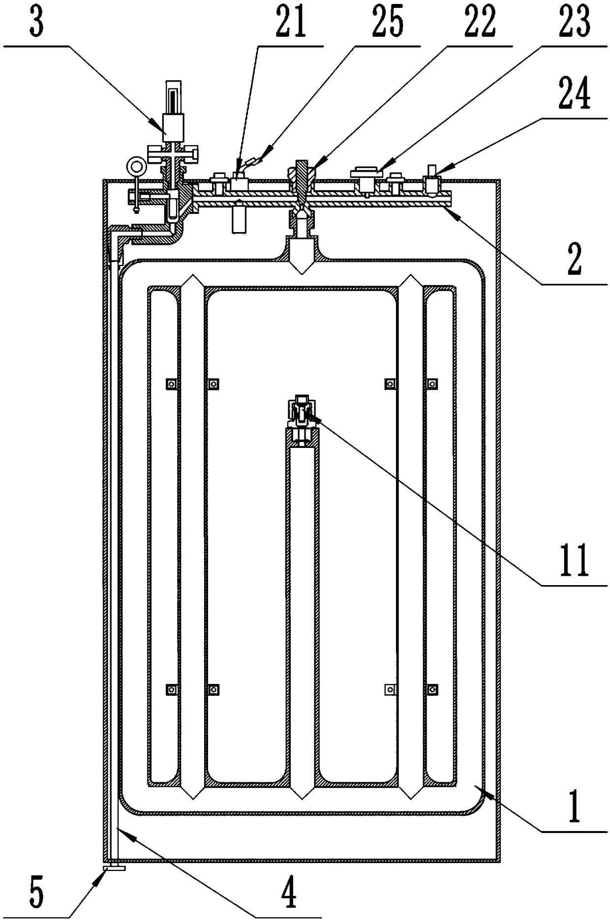
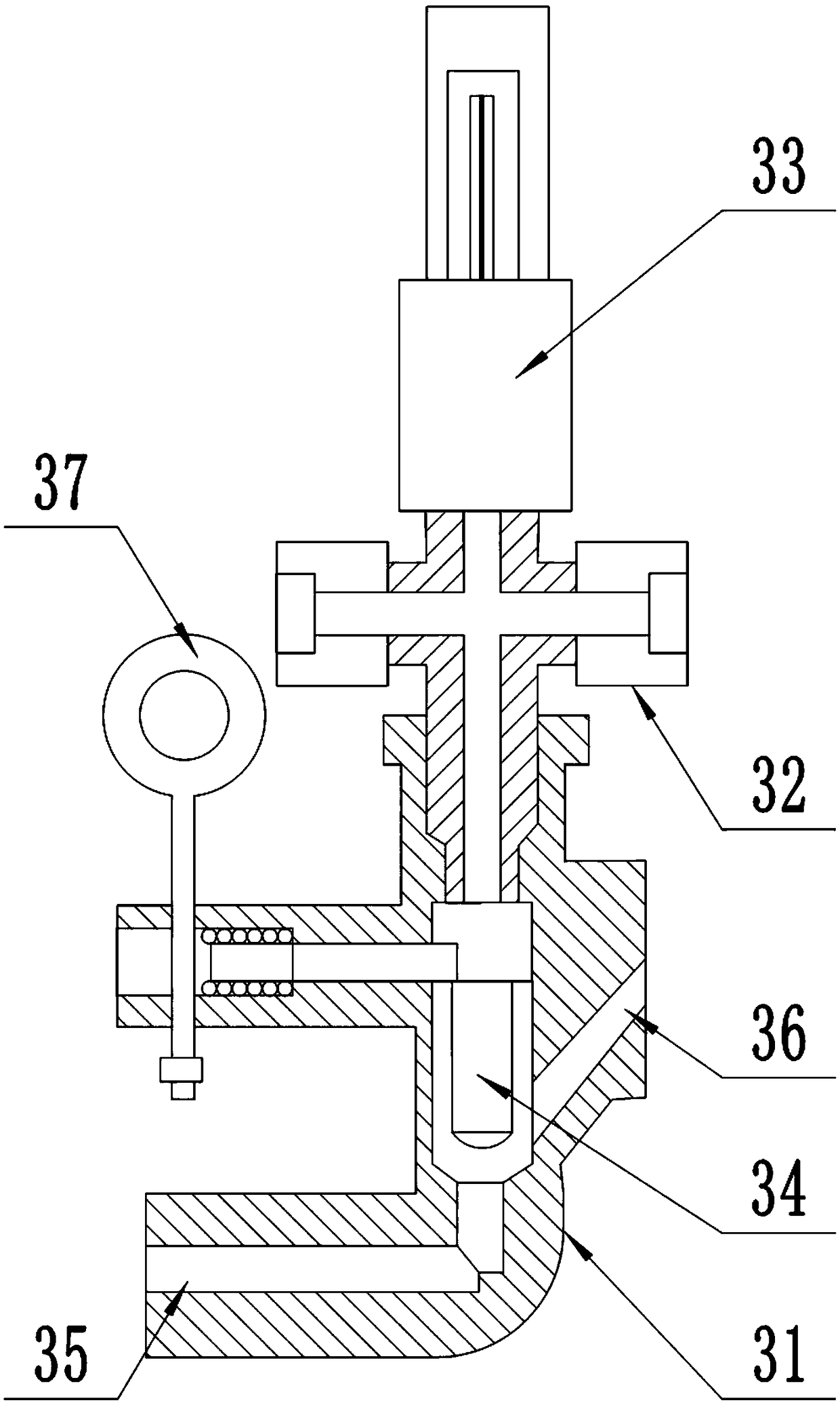
[0033] Example 1: Please refer to Figure 1-3 , a temperature detection automatic fire extinguishing device, comprising:

[0034] A gas storage container 1 for storing fire extinguishing agent;

[0035] Fire extinguishing agent pipe 2 for switching and transporting fire extinguishing agent, the fire extinguishing agent pipe is connected to the gas storage container;

[0036] A temperature-sensing fire extinguishing valve 3 for temperature sensing and controlling the flow of fire extinguishing agent is installed at one end of the fire extinguishing agent pipe;

[0037] The release pipe 4 is used to deliver the fire extinguishing agent passing through the temperature-sensitive fire extinguishing valve to the nozzle for outward release, one end of which is connected to the temperature-sensitive fire extinguishing valve, and the other end is equipped with a nozzle 5;

[0038] The temperature-sensitive fire extinguishing valve 3 includes a valve body 31, a four-way joint 32 and a...

Embodiment 2

[0048] Example 2: Please refer to Figure 4 The difference between this embodiment and Embodiment 1 is that it includes at least two temperature-sensing automatic fire extinguishing devices 200 connected through compressed air pipes 201, wherein the joints at the left and right ends of the four-way joints of each temperature-sensing automatic fire extinguishing device At least one of the joints is externally connected to the four-way joint of another temperature detection automatic fire extinguishing device through a compressed air pipe, and the joints not connected to the compressed air pipe are sealed; the four-way joint and the compressed air pipe are filled with compressed gas.

[0049] In this embodiment, when the present invention is used for two cabinets or multiple cabinets, when the ambient temperature in the protection zone of the cabinet on fire reaches the set temperature of 68°C, the temperature at the rear end of the temperature detection and automatic fire exting...

Embodiment 3

[0050] Example 3: Please refer to Figure 5 , including a temperature detection automatic fire extinguishing device 300, the outer rear end of the integrated shell of the temperature detection automatic fire extinguishing device is equipped with a closed four-way joint, a signal feedback terminal, a main switch of the air outlet, a pressure gauge and a fire detection pipe interface.

[0051] The difference between this embodiment and Embodiment 1 is that in this embodiment, the glass bulb temperature probe of the temperature-sensitive fire extinguishing valve is removed, and a fire detection pipe 301 is installed and connected to the fire detection pipe interface. When this embodiment is only used for a single cabinet, when the fire detection tube in the fire protection area senses the fire source signal (160°C ± 10°C), the gas in the fire detection tube of the fire cabinet will expand rapidly, and finally will be randomly distributed in the pipeline. A nozzle is blasted out ...


PUM


Abstract

The invention discloses a heat detection automatic fire extinguishing device. The heat detection automatic fire extinguishing device comprises a gas storage container, a fire extinguishing agent pipe,a temperature sensing fire valve and a release pipe, wherein the gas storage container is used for storing a fire extinguishing agent; the fire extinguishing agent pipe is used for being opened and closed to deliver the fire extinguishing agent and communicates with the gas storage container; the temperature sensing fire valve is used for sensing the temperature and controlling circulation of thefire extinguishing agent and is mounted at one end of the fire extinguishing agent pipe; the release pipe is used for delivering the fire extinguishing agent passing through the temperature sensing fire valve to a spray head to release outwards, one end of the release pipe is connected to the temperature sensing fire valve, and the other end of the release pipe is provided with the spray head. The heat detection automatic fire extinguishing device achieves the purposes of front temperature sensing and back fire extinguishing through the special temperature sensing fire valve, effectively andaccurately extinguishes the fire at the front high-temperature point and improves the fire extinguishing efficiency. Moreover, the heat detection automatic fire extinguishing device can be connected with multiple devices in parallel to realize linkage protection between multiple protection areas or the multiple devices. Once one device detects a fire point, the multiple devices connected in parallel starts simultaneously to conduct fire extinguishing so as to control the fire intensity, and the safety of facilities in the protection areas can be protected better.

Description

technical field [0001] The invention relates to the field of fire-fighting equipment, in particular to a temperature-sensing detection automatic fire-extinguishing device. Background technique [0002] As an advanced fire extinguishing device, the temperature detection automatic fire extinguishing device has attracted much attention in the field of fire safety in server groups, power distribution rooms, electrical cabinets, mobile communication base stations and other facilities. The temperature detection automatic fire extinguishing device belongs to the fixed non-electric self-starting fire extinguishing device. This type of fire extinguishing device does not need power supply and traditional fire detection and alarm equipment. The whole device is often composed of a temperature detection device or a flexible fire detection tube. The starting method It is divided into two types: temperature-sensitive glass ball start-up and fire-detecting tube rupture start-up. [0003] S...

Claims


Application Information

Patent Timeline
IPC IPC(8): A62C35/10A62C35/11
CPCA62C35/10A62C35/11
Inventor 李荣春
Owner 广东固稳科技有限公司
Learn More