Stepped type pouring device

A stepped, straight sprue technology, applied in the direction of casting molding equipment, molds, cores, etc., can solve the problems of high bottom temperature, poor feeding effect, and can not guarantee the ideal state, etc., to improve the feeding distance, Guaranteeing the quality of castings and reducing costs

Pending Publication Date: 2019-02-12
HUSN CASTING ANHUI YINGLIU GROUP
View PDF0 Cites 7 Cited by
  • Summary
  • Abstract
  • Description
  • Claims
  • Application Information

AI Technical Summary

Problems solved by technology

However, in the commonly used bottom pouring gating system, even if the horizontal surface of the molten metal reaches the gate position of the middle layer and the highest layer, the molten metal still enters from the bottom gate position, which makes the bottom temperature higher, so the temperature from the bottom up cannot be guaranteed. Higher and higher ideals make feeding less effective

Method used


Image

  • Stepped type pouring device
  • Stepped type pouring device
  • Stepped type pouring device

Examples


Embodiment 1

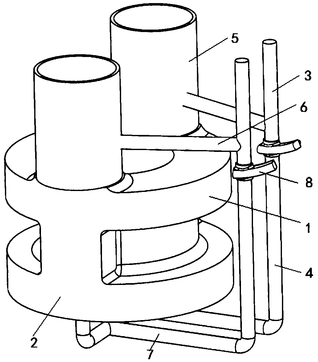
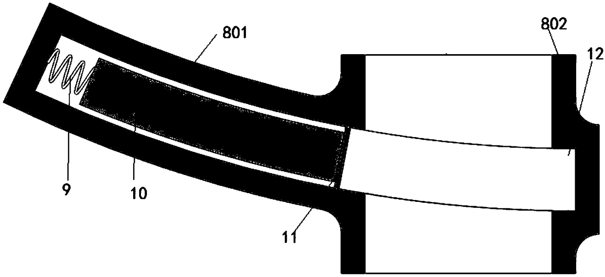
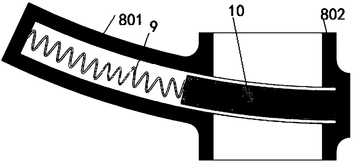
[0021] see Figure 1-3 As shown, a stepped pouring device includes an upper casting cavity 1, a lower casting cavity 2, an upper sprue 3, and a lower sprue 4. The upper casting cavity 1 communicates with the lower casting cavity 2, and the upper casting The upper end of the cavity 1 is provided with a riser 5, the riser 5 is connected with the upper sprue 6, the upper sprue 6 is connected with the upper sprue 3, the lower casting cavity 2 is connected with the bottom sprue 7, and the lower end of the lower sprue 3 It communicates with the bottom sprue 7, and the upper sprue 3 and the lower sprue 4 are connected by a flow interceptor. The interceptor includes a T-shaped cast pipe 8, and the T-shaped cast pipe 8 is composed of a horizontal pipe 801 and a vertical pipe 802. The two ends of 802 are respectively connected with the upper sprue 3 and the lower sprue 4 , the horizontal tube 801 is provided with a spring 9 , and the spring 9 is fixedly connected with the stopper 10 . ...

Embodiment 2

[0023] see figure 1 , 4 As shown, a stepped pouring device includes an upper casting cavity 1, a lower casting cavity 2, an upper sprue 3, and a lower sprue 4. The upper casting cavity 1 communicates with the lower casting cavity 2, and the upper casting The upper end of the cavity 1 is provided with a riser 5, the riser 5 is connected with the upper sprue 6, the upper sprue 6 is connected with the upper sprue 3, the lower casting cavity 2 is connected with the bottom sprue 7, and the lower end of the lower sprue 3 It communicates with the bottom sprue 7, and the upper sprue 3 and the lower sprue 4 are connected by a flow interceptor. The interceptor includes a T-shaped cast pipe 8, and the T-shaped cast pipe 8 is composed of a horizontal pipe 801 and a vertical pipe 802. The two ends of 802 are respectively connected with the upper sprue 3 and the lower sprue 4, the end of the horizontal tube 801 away from the vertical tube 802 is provided with an end cover 13, the horizont...


PUM


Abstract

The invention discloses a stepped type pouring device. The stepped type pouring device comprises an upper-layer casting molding cavity, a lower-layer casting molding cavity, upper sprues and lower sprues. The upper-layer casting molding cavity communicates with the lower-layer casting molding cavity. Risers are formed in the upper end of the upper-layer casting molding cavity. The risers communicate with upper-layer pouring gates. The upper-layer pouring gates communicate with the upper sprues. The lower-layer casting molding cavity communicates with bottom-layer pouring gates. The lower endsof the lower sprues communicate with the bottom-layer pouring gates. The upper sprues are connected with the lower sprues through cut-off devices. Each cut-off device comprises a T-shaped cast pipe. Each T-shaped cast pipe is composed of a transverse pipe and a vertical pipe. Each transverse pipe communicates with a corresponding vertical pipe. The two ends of each vertical pipe are connected witha corresponding upper sprue and a corresponding lower sprue respectively. A spring is arranged in each transverse pipe. Each spring is fixedly connected with a blocking block. A soluble blocking needle is arranged at the end, away from a corresponding spring, of each blocking block. A groove is formed in the inner wall of each vertical pipe, and each groove is matched with a corresponding blocking block. By means of the stepped type pouring device, the temperature of positions of the risers are the highest; sequential solidification of castings is achieved; and feeding distance of the risersis improved greatly.

Description

technical field [0001] The invention relates to a pouring device, in particular to a stepped pouring device. Background technique [0002] Some casting processes require a gating system that adopts a stepped pouring method. Ideally, the stepped pouring method should be that the liquid metal enters the mold cavity from the gate at the bottom position, and then enters the mold cavity from a higher layer. Finally, it enters from the riser at the highest position, so that the temperature of the liquid metal at the lowest position in the mold cavity is the lowest, and the temperature increases gradually upwards, and the temperature at the riser of the upper box is the highest, so that the purpose of sequential solidification to ensure feeding can be achieved. However, in the commonly used bottom pouring gating system, even if the horizontal surface of the molten metal reaches the gate position of the middle layer and the highest layer, the molten metal still enters from the botto...

Claims


Application Information

Patent Timeline
Patent Type & Authority Applications(China)
IPC IPC(8): B22C9/08
CPCB22C9/082
Inventor 王成龙李勇俞秀枝金慧谭野
Owner HUSN CASTING ANHUI YINGLIU GROUP
Why Eureka
Try Eureka