A Method for Reducing Turbine Blade Looseness of Gas Turbine
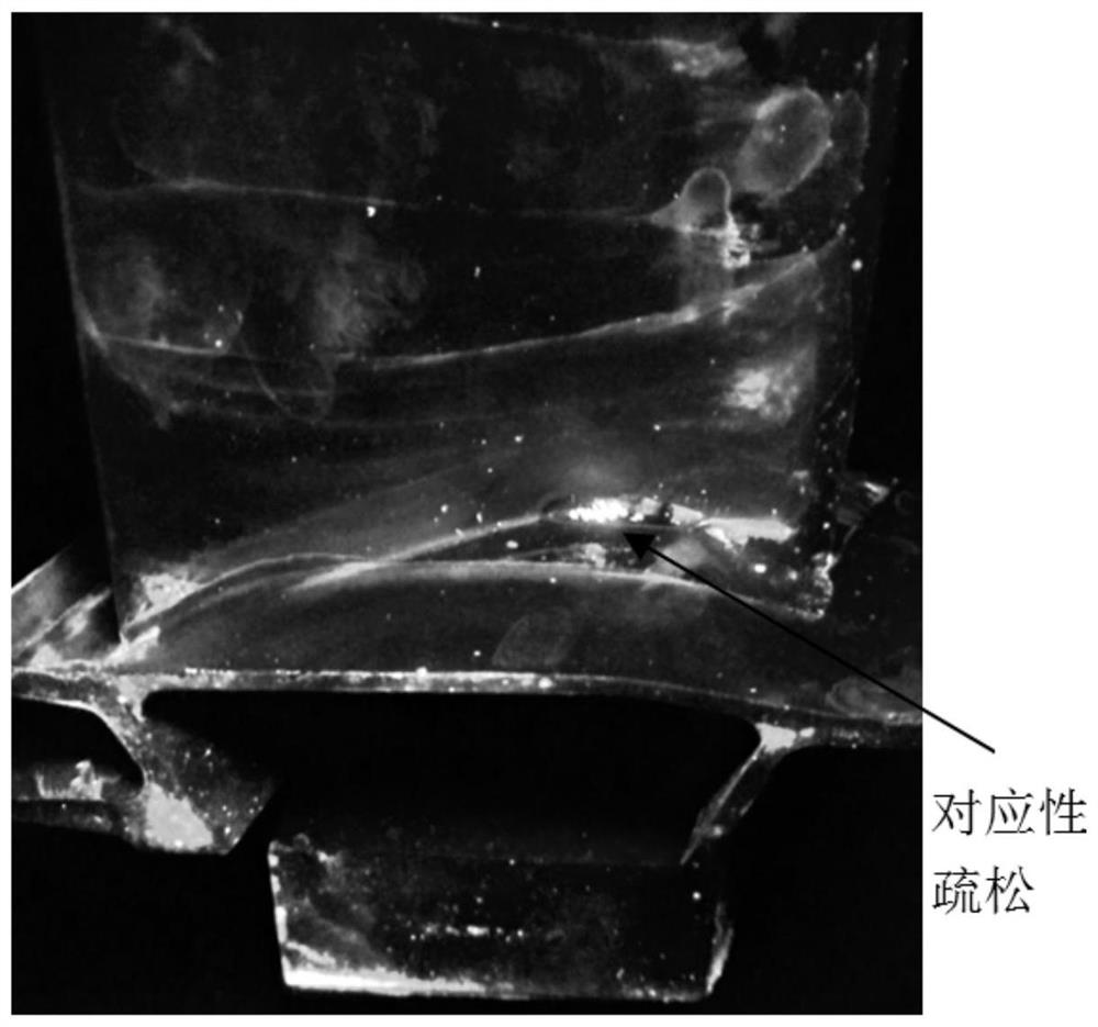
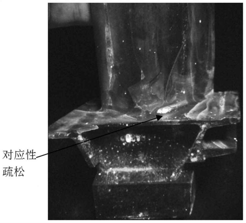
A technology of turbine blades and gas turbines, which is applied to casting molding equipment, casting mold components, manufacturing tools, etc., can solve problems such as complex blade structures, and achieve the effects of improving cooling methods, reducing micro-porosity, and eliminating porosity
- Summary
- Abstract
- Description
- Claims
- Application Information
AI Technical Summary
Problems solved by technology
Method used
Image
Examples
Embodiment 1
[0030] In this embodiment, the ЧС70-ВИ alloy is taken as an example. The method for reducing the looseness of the turbine blades of the gas turbine according to the present invention includes the following steps:
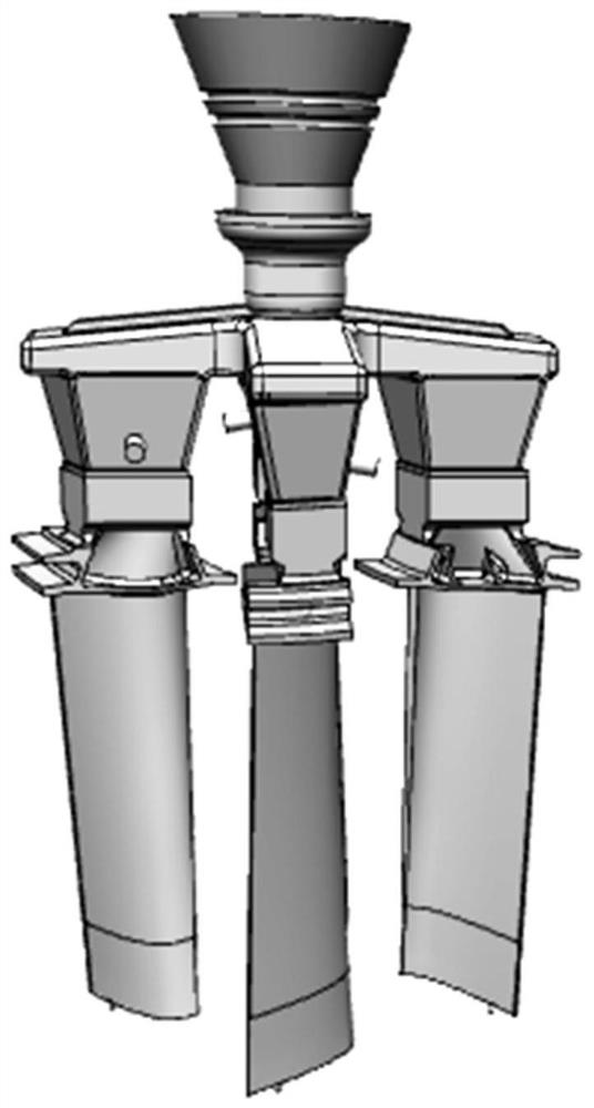
[0031] 1) Prepare the gas turbine blade wax mold, wherein the height of the riser of the gas turbine blade wax mold is 1 / 5 to 1 / 6 of the total length of the gas turbine blade, and then use the automatic line full silica sol through the gas turbine blade wax mold Prepare turbine blade formwork;
[0032] 2) Wrap three layers of ceramic wool around the turbine blade formwork, wherein the thickness of each layer of ceramic wool is 6mm, the first layer of ceramic wool is located between the lower end of the ceramic sprue cup and the riser, and the second layer of ceramic wool is located between the ceramic pouring cup and the riser. Between the lower end of the beaker and 1 / 3 of the leaf body, the third layer of ceramic cotton is located between the lower end of the cera...
Embodiment 2
[0036] In this embodiment, the ЧС70-ВИ alloy is taken as an example. The method for reducing the looseness of the turbine blades of the gas turbine according to the present invention includes the following steps:
[0037] 1) Prepare the gas turbine blade wax mold, wherein the height of the riser of the gas turbine blade wax mold is 1 / 5 to 1 / 6 of the total length of the gas turbine blade, and then use the automatic line full silica sol through the gas turbine blade wax mold Prepare turbine blade formwork;
[0038] 2) Wrap three layers of ceramic wool around the turbine blade formwork, wherein the thickness of each layer of ceramic wool is 6mm, the first layer of ceramic wool is located between the lower end of the ceramic sprue cup and the riser, and the second layer of ceramic wool is located between the ceramic pouring cup and the riser. Between the lower end of the beaker and 1 / 3 of the leaf body, the third layer of ceramic cotton is located between the lower end of the cera...
Embodiment 3
[0042] In this embodiment, the ЧС70-ВИ alloy is taken as an example. The method for reducing the looseness of the turbine blades of the gas turbine according to the present invention includes the following steps:
[0043] 1) Prepare the gas turbine blade wax mold, wherein the height of the riser of the gas turbine blade wax mold is 1 / 5 to 1 / 6 of the total length of the gas turbine blade, and then use the automatic line full silica sol through the gas turbine blade wax mold Prepare turbine blade formwork;
[0044] 2) Wrap three layers of ceramic wool around the turbine blade formwork, wherein the thickness of each layer of ceramic wool is 6mm, the first layer of ceramic wool is located between the lower end of the ceramic sprue cup and the riser, and the second layer of ceramic wool is located between the ceramic pouring cup and the riser. Between the lower end of the beaker and 1 / 3 of the leaf body, the third layer of ceramic cotton is located between the lower end of the cera...
PUM
| Property | Measurement | Unit |
|---|---|---|
| thickness | aaaaa | aaaaa |
Abstract
Description
Claims
Application Information
 - R&D
- Intellectual Property
- Life Sciences
- Materials
- Tech Scout
- Unparalleled Data Quality
- Higher Quality Content
- 60% Fewer Hallucinations
Browse by: Latest US Patents, China's latest patents, Technical Efficacy Thesaurus, Application Domain, Technology Topic, Popular Technical Reports.
© 2025 PatSnap. All rights reserved.Legal|Privacy policy|Modern Slavery Act Transparency Statement|Sitemap|About US| Contact US: help@patsnap.com


