Industrial robot with pickup function

An industrial robot and functional technology, applied in manipulators, manufacturing tools, program-controlled manipulators, etc., can solve problems such as increasing the working range of robots, inability to rotate and move, and reducing work efficiency, saving manpower and material resources, and improving stability and efficiency. , the effect of improving usability

Inactive Publication Date: 2019-02-12
苏子程
View PDF0 Cites 10 Cited by
  • Summary
  • Abstract
  • Description
  • Claims
  • Application Information

AI Technical Summary

Problems solved by technology

The existing installation base has a simple structure and cannot be rotated or moved, which makes it inconvenient to increase the working range of the robot and reduce work efficiency

Method used


Image

  • Industrial robot with pickup function
  • Industrial robot with pickup function
  • Industrial robot with pickup function

Examples


Embodiment 1

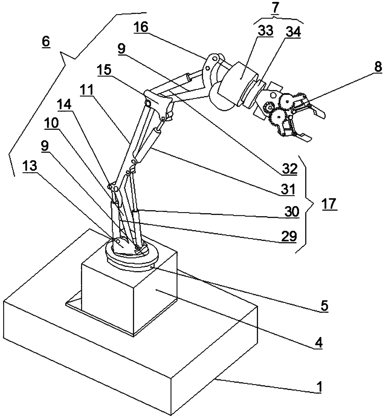
[0028] Such as Figure 1-4 As shown, the tablet pressing and molding device for medicine production according to the embodiment of the present invention includes a base 1. The inner and lower ends of the base 1 are respectively provided with a pneumatic mechanism 2 and a moving mechanism 3, and the upper end of the base 1 is provided with The fixed seat 4 is provided with a rotating mechanism 5 in the middle of the upper end of the fixed seat 4, and the upper end of the rotating mechanism 5 is respectively provided with a matching connecting mechanism 6, a rotating mechanism 7 and a clamping mechanism 8. The mechanism 6 is located at the upper end of the rotating mechanism 5, the upper end of the connecting mechanism 6 away from the rotating mechanism 5 is provided with the clamping mechanism 8, between the clamping mechanism 8 and the connecting mechanism 6 There is the second rotating mechanism 7, and the clamping mechanism 8 is provided at one end of the connecting mechanism...

Embodiment 2

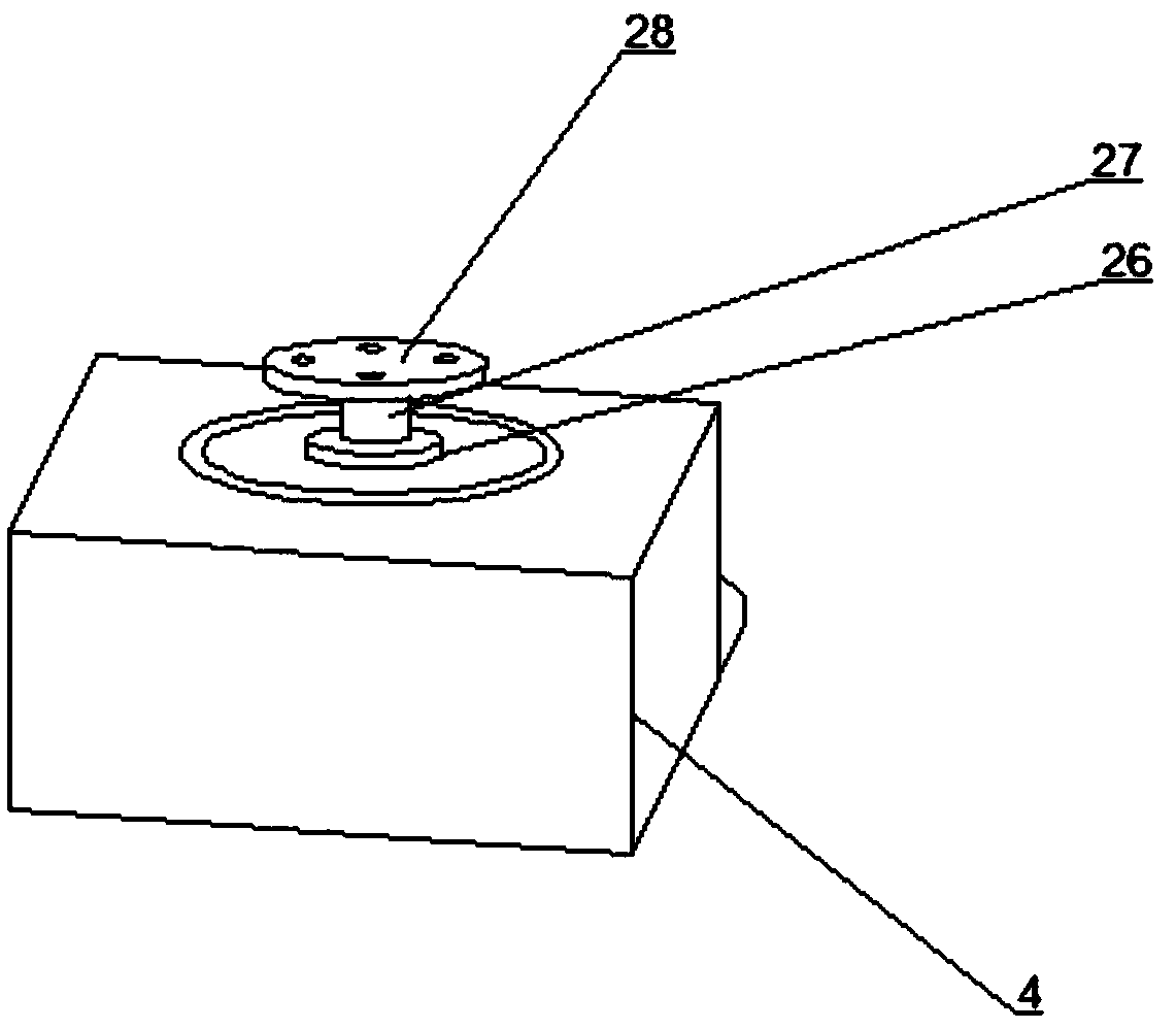
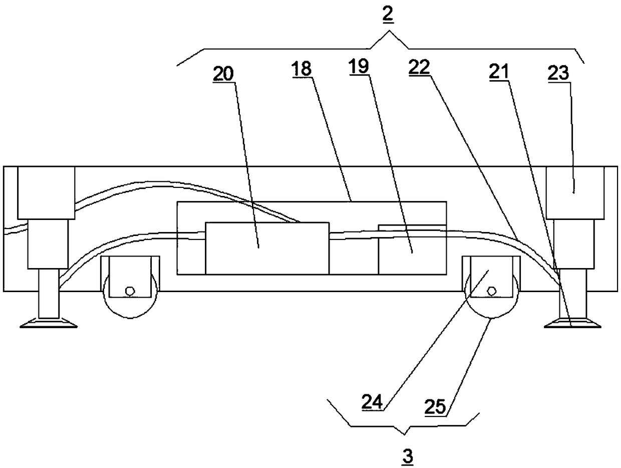
[0031] Such as Figure 1-4 As shown, the pneumatic mechanism 2 includes a placing frame 18 located inside the base 1, a controller 19 and an air pump 20 are respectively provided at both ends of the placing frame 18, and a fixed suction cup is provided at the through hole of the base 1 21. Between the air rod on the fixed suction cup 21 and the air pump 20, there are air pipes 22 that penetrate both sides of the placing frame 18. The inside of the base 1 and on both sides of the placing frame 18 are provided with lifting rods 23, and the lower ends of the lifting rods 23 are connected with the ventilation rods on the fixed suction cup 21. The moving mechanism 3 includes roller brackets 24 located in the grooves on both sides of the lower end of the base 1, and the lower part of the roller bracket 24 is provided with moving rollers 25. The rotating mechanism 5 includes a bearing 26 located in the middle of the upper end of the fixed seat 4, and the middle of the bearing 26 is s...

Embodiment 3

[0033] Such as Figure 1-4 As shown, the clamping mechanism 8 includes a connecting plate 35 located at one end of the second rotating base 34, one end of the connecting plate 35 is provided with a second motor 36, and the driving shaft of the second motor 36 is provided with the connecting plate inserted therethrough There is a hollow drive gear 37 on the middle side of the 35. The connecting plate 35 is far away from the second motor 36 and is provided with a driven gear 38 and a driven gear 39 on both sides. One end is matched with a clamping claw 40 provided with one end, and one end of the driven gear 39 is matched with a second clamping claw 41 provided with one end. A distance measuring infrared camera 42 is arranged on the clamping mechanism 8 in the middle of the connecting plate 35.

[0034] Working principle: When in use, by setting the moving mechanism 3 under the base 1, the base 1 and the base 1 can move the entire robot, so as to achieve the displacement effect, a...


PUM


Abstract

The invention discloses an industrial robot with a pickup function. The industrial robot with the pickup function comprises a base. A pneumatic mechanism and a moving mechanism are arranged in the base and at the lower end of the base correspondingly. The upper end of the base is provided with a fixed seat. A rotating mechanism I is arranged in the middle of the upper end of the fixed seat. The upper end of the rotating mechanism I is provided with a connecting mechanism, a rotating mechanism II and a clamping mechanism which are matched. The connecting mechanism comprises a connecting seat connected with the rotating mechanism I, a connecting arm I, a connecting arm II and a connecting arm III. The connecting arm I is connected with the connecting seat through a connecting part I. The connecting arm II is connected with the connecting arm I through a connecting part II. The connecting arm III is connected with the connecting arm II through a connecting part III. The connecting arm IIIis connected with the rotating mechanism II through a connecting part IV. The connecting I, the connecting arm II and the connecting arm III are connected through telescopic driving devices in a matched mode. The industrial robot with the pickup function has the beneficial effects of realizing multi-angle and multi-position adjustment changes during operation, and the practicality of the industrial robot is improved.

Description

Technical field [0001] The invention relates to the technical field of industrial machinery, in particular to an industrial robot with a picking function. Background technique [0002] With the continuous development of science and technology, various industrial robots used in industry appear in daily production. Industrial robots have high working efficiency, good safety performance, low cost, and high precision of production and processing. The goods grabbing device of industrial robots is commonly used in production to grab and transport goods. [0003] However, the existing cargo grabbing devices for industrial robots still have certain shortcomings in use. The existing cargo grabbing device for industrial robots has a simple structure and insufficient stability performance when grabbing objects, resulting in cargo damage. The existing installation base has a simple structure and cannot be rotated or moved, which is inconvenient to increase the working range of the robot and...

Claims


Application Information

Patent Timeline
Patent Type & Authority Applications(China)
IPC IPC(8): B25J9/00B25J15/02B25J15/08
CPCB25J9/00B25J15/0213B25J15/08
Inventor 苏子程
Owner 苏子程
Why Eureka
Try Eureka