Combined mold for producing prefabricated parts

A technology of prefabricated components and combined molds, applied in the direction of molds, etc., can solve the problems of low mold utilization rate, reduce factory production efficiency, and increase production costs, so as to improve common rate and service cycle, reduce mold cost input, and improve production efficiency effect

Pending Publication Date: 2019-02-12
CHANGSHA HOME BROAD HOMES IND JIANGSU CO LTD
View PDF12 Cites 1 Cited by
  • Summary
  • Abstract
  • Description
  • Claims
  • Application Information

AI Technical Summary

Problems solved by technology

[0002] At present, the molds used to produce prefabricated components are complex in structure and heavy in weight, and for different sizes of prefabricated components, it is necessary to order molds of corresponding specifications, and the sizes of prefabricated components used in various construction projects are different, and the poor versatility of the molds leads to The utilization rate of molds is low, and the cost of molds remains high, which not only wastes resources, but also requires a special warehouse to store molds with low utilization rates, which increases management and storage costs
Such as patent document 1 (publication number: CN107553696A) discloses a kind of molding die and forming method of the rib prefabricated component, such as the patent document figure 1 As shown, the mold ribs on the left and right sides in the figure are located between the mold ribs on the upper and lower sides. The length of the mold ribs on the left and right sides determines the width of the prefabricated component. When producing prefabricated component products for different projects, The length and width of prefabricated components may change. At this time, all the molds on the assembly line need to be replaced, resulting in low mold utilization. At the same time, the mold replacement process will greatly reduce the production efficiency of the factory
In addition, when the mold is installed, it is necessary to pre-mark the installation position of the mold on the workbench to improve the installation accuracy. In this way, every time the mold is replaced, the process of marking, assembling, and fixing the mold must be carried out. The installation process is time-consuming and labor-intensive. Meet the requirements of today's on-demand production
[0003] In addition, existing prefabricated component molds have reinforcement holes / slots for protruding steel bars, and the spacing between the reinforcement holes / slots is constant. Once the spacing of the distributed steel bars needs to be adjusted, the previous mold It must be scrapped, which not only causes serious waste, but also increases production costs, which is not conducive to improving production efficiency.

Method used


Image

  • Combined mold for producing prefabricated parts
  • Combined mold for producing prefabricated parts
  • Combined mold for producing prefabricated parts

Examples


Embodiment Construction

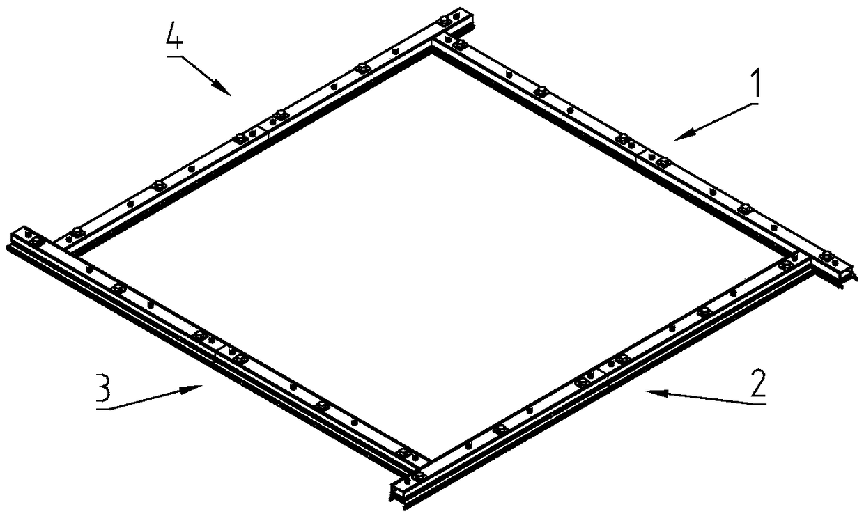
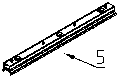
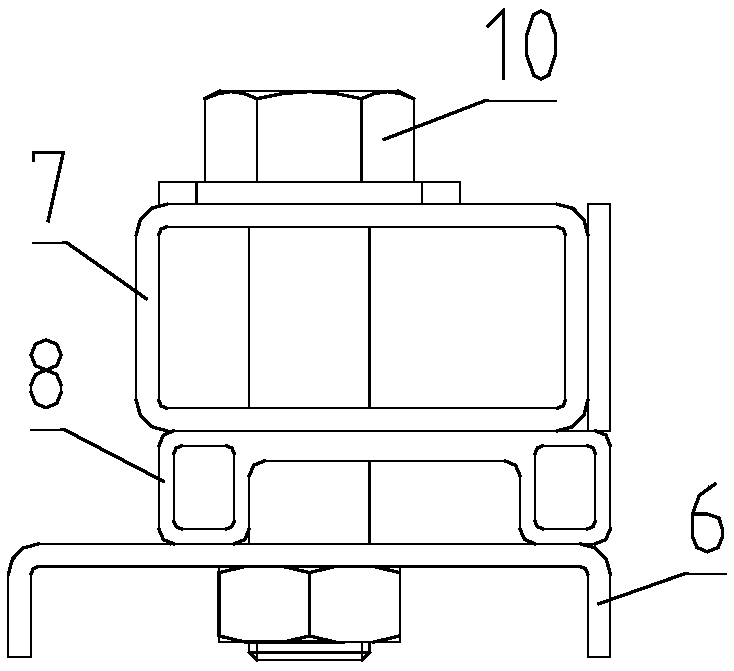
[0022] The present invention will be described in further detail below in conjunction with the accompanying drawings.

[0023] see Figure 1-6 , a combination mold for producing prefabricated components, which includes a first mold rib 1, a second mold rib 2, a third mold rib 3 and a fourth mold rib 4, the first mold rib 1. The second mold rib 2, the third mold rib 3 and the fourth mold rib 4 all have rib surfaces for abutting against prefabricated components, and the second mold rib 2 is perpendicular to the first mold One end of the rib 1 and the second mold rib 2 abuts against the rib surface of the first mold rib 1 , and the third mold rib 3 is perpendicular to the second mold rib 2 And one end of the third mold rib 3 abuts against the rib surface of the second mold rib 2, the fourth mold rib 4 is perpendicular to the third mold rib 3 and the fourth mold rib One end of the side 4 abuts against the rib surface of the third mold rib 3, the first mold rib 1 is perpendicular...


PUM


Abstract

The invention discloses a combined mold for producing prefabricated parts. A second mold flange is perpendicular to a first mold flange, and one end part of the second mold flange is abutted against aflange surface of the first mold flange; a third mold flange is perpendicular to a second mold flange, and one end part of the third mold flange is abutted against the flange surface of the second mold flange; a fourth mold flange is perpendicular to the third mold flange, and one end part of the fourth mold flange is abutted against the flange surface of the third mold flange; the first mold flange is perpendicular to the fourth mold flange, and one end part of the first mold flange is abutted against the flange surface of the fourth mold flange. The combined mold can well adapt to production requirements of various specifications of prefabricated parts, a mold flange does not need to be replaced when the size of the prefabricated parts to be produced is changed as long as the positionsof the four flanges of molds are properly adjusted, so that the production efficiency is greatly improved, and a utilization rate of the molds is improved.

Description

technical field [0001] The invention relates to the technical field of construction engineering, in particular to a combination mold for producing prefabricated components. Background technique [0002] At present, the molds used to produce prefabricated components are complex in structure and heavy in weight, and for prefabricated components of different sizes, it is necessary to order molds of corresponding specifications. The utilization rate of molds is low, and the cost of molds remains high, which not only wastes resources, but also requires a special warehouse to store molds with low utilization rates, which increases management and storage costs. Such as patent document 1 (publication number: CN107553696A) discloses a kind of molding die and forming method of the rib prefabricated component, such as the patent document figure 1 As shown, the mold ribs on the left and right sides in the figure are located between the mold ribs on the upper and lower sides. The length...

Claims


Application Information

Patent Timeline
Patent Type & Authority Applications(China)
IPC IPC(8): B28B7/02
CPCB28B7/02
Inventor 张剑王雅明李融锋徐雷周涛
Owner CHANGSHA HOME BROAD HOMES IND JIANGSU CO LTD
Why Eureka
Try Eureka