Conveying device

A technology of conveying device and conveying mechanism, which is applied to conveyor objects, transportation and packaging, roller tracks, etc., can solve the problem of inconvenient reversing of conveyed objects, and achieve the effect of reducing the demand for site area.

Active Publication Date: 2019-02-12
DONGXU OPTOELECTRONICS TECH CO LTD
View PDF8 Cites 8 Cited by
  • Summary
  • Abstract
  • Description
  • Claims
  • Application Information

AI Technical Summary

Problems solved by technology

[0003] The purpose of the present invention is to provide a transmission device to overcome the inconvenience of reversing the conveying objects on the assembly line in the prior art.

Method used


Image

  • Conveying device
  • Conveying device
  • Conveying device

Examples


Embodiment Construction

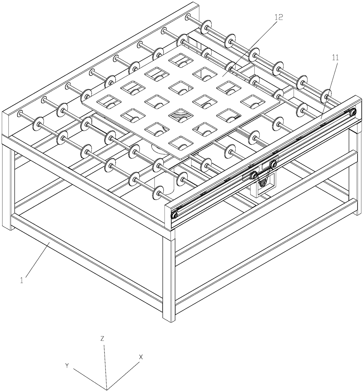
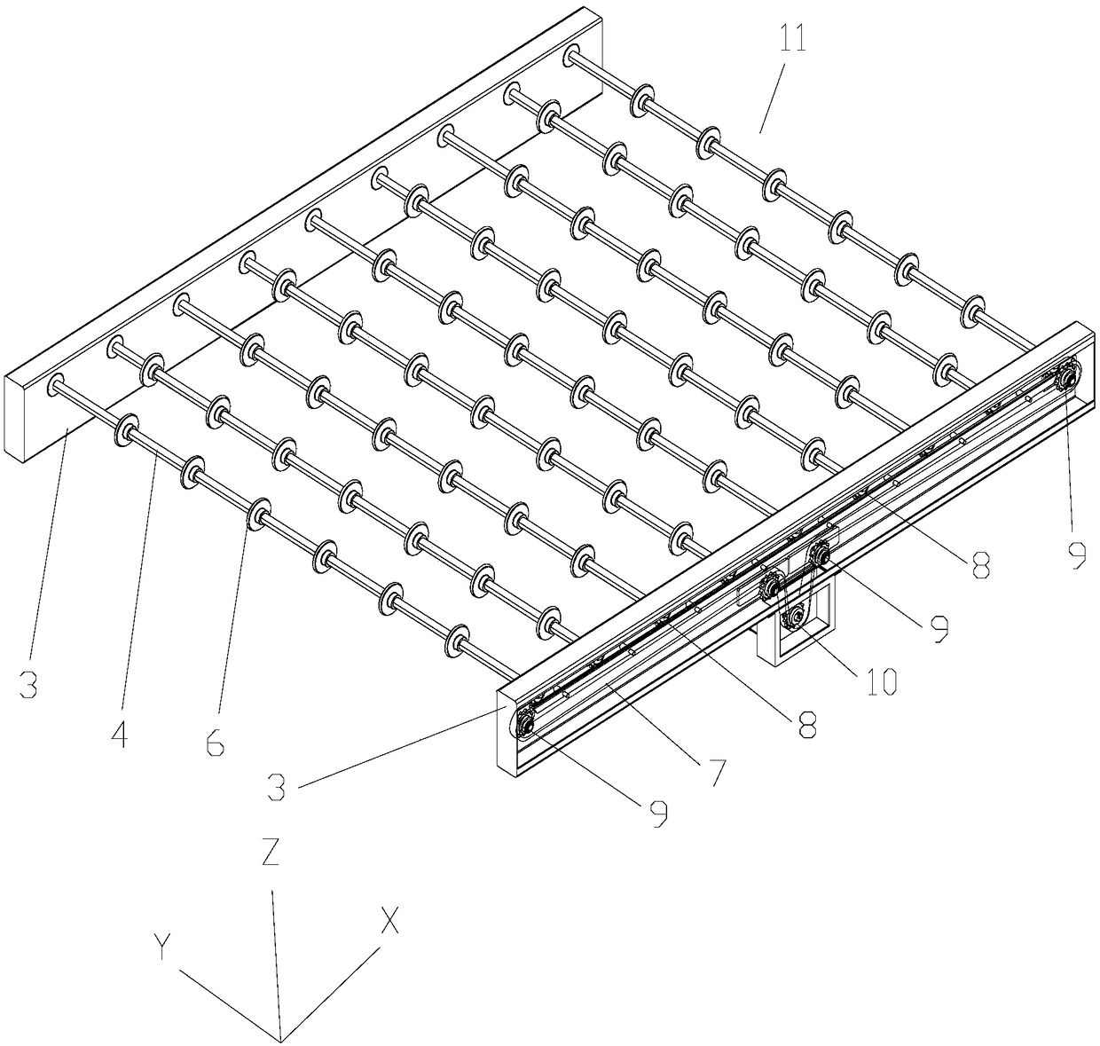
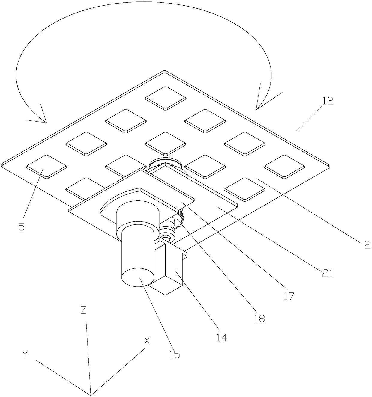
[0021] The present application provides a conveying device, which includes a frame 1 and a first conveying mechanism 11 and a second conveying mechanism 12 arranged on the frame 1, the first conveying mechanism 11 is used to drive objects along the X The second transmission mechanism 12 includes a supporting plate 2, a lifting unit and a rotating unit, the supporting plate 2 can support the object, and the lifting unit can lift the supporting plate 2 along the Z axis so that the The support plate 2 is switched between a first position and a second position higher than the first position, and the rotation unit can drive the support plate 2 to rotate in the plane formed by the X axis and the Y axis, wherein, in During the process of moving from the first position to the second position, the support plate 2 can lift the object on the first conveying mechanism 11, and when moving from the second position to the In the process of the first position, the lifting unit can re-place th...


PUM


Abstract

The invention relates to the field of assembly lines of battery packs, and discloses a conveying device. The conveying device comprises a rack (1) a first conveying mechanism (11) and a second conveying mechanism (12), wherein the first conveying mechanism (11) and the second conveying mechanism (12) are arranged on the rack; the first conveying mechanism is used for driving an object to move in an X axis direction; the second conveying mechanism comprises a supporting plate (2), a lifting unit and a rotating unit; the lifting unit is capable of lifting the supporting plate along a Z axis, andthe supporting plate can be driven to rotate through the rotating unit; when moving from a first position to a second position, the supporting plate is capable of propping an object on the first conveying mechanism; and when moving from the second position to the first position, the lifting unit is capable of placing the object on the first conveying mechanism again in order to continuously drivethe object to move in the X axis direction though the first conveying mechanism. With the adoption of the conveying device, the object conveyed on an assembly line can be turned, and moreover, the demand on the field area can be reduced.

Description

technical field [0001] The invention relates to the field of battery assembly lines, in particular to a conveying device. Background technique [0002] In the assembly line production of products, including the assembly line production of thin-film solar cell modules, when the product moves along the assembly line, it is usually necessary to perform a steering operation at a certain angle. At present, the device that can complete this operation is not flexible and occupies too much space. It is necessary to improve it. Contents of the invention [0003] The object of the present invention is to provide a conveying device in order to overcome the problem of inconvenient reversing of conveyed objects on the assembly line existing in the prior art. [0004] In order to achieve the above object, the present invention provides a conveying device on the one hand, the conveying device includes a frame and a first conveying mechanism and a second conveying mechanism arranged on t...

Claims


Application Information

Patent Timeline
Patent Type & Authority Applications(China)
IPC IPC(8): B65G47/244B65G13/00
CPCB65G13/00B65G47/244
Inventor 李腾刘文泰曾庆祥张增民
Owner DONGXU OPTOELECTRONICS TECH CO LTD
Why Eureka
Try Eureka