Self-adaptive locking mechanism for box body

A locking mechanism and self-adaptive technology, which is applied in the direction of locking equipment, building structures, building fastening devices, etc., can solve the problem that the axial output force of the locking mechanism meets the target requirements, limited space size, and processing errors Problems such as large locking force and pull-out force of the locking mechanism achieve the effects of low installation difficulty, reasonable structure distribution, and less reprocessing procedures

Pending Publication Date: 2019-02-12
GUIZHOU AEROSPACE TIANMA ELECTRICAL TECH
View PDF7 Cites 8 Cited by
  • Summary
  • Abstract
  • Description
  • Claims
  • Application Information

AI Technical Summary

Problems solved by technology

[0004] a) The structural size of the locking mechanism: the locking mechanism is installed in the inner cavity of the arc-shaped bracket of the support platform, which is limited by the space size of the inner cavity of the arc-shaped bracket, in order to meet the requirements of the axial telescopic stroke of the locking pin , it is often necessary to design a special mechanism to meet the size and action requirements;
[0005] b) The selection of power components of the locking mechanism: during the process of the locking pin extending into and out of the pin hole of the box body, the processing error and work deformation of the pin hole of the box body, and the assembly error of each part make the locking mechanism required The locking force and ejection force are relatively large. Under the premise of limited space and based on existing energy sources, it is difficult to solve the problem that the axial output force of the locking mechanism meets the target requirements.
[0006] c) Locking problem during the working process: During the working process, the locking pins are required to move synchronously and all locking pins can fully fit the inner wall of the pin hole of the locked box in the axial direction under the locked state

Method used


Image

  • Self-adaptive locking mechanism for box body
  • Self-adaptive locking mechanism for box body
  • Self-adaptive locking mechanism for box body

Examples


Embodiment Construction

[0024] The technical solution of the present invention is further described below, but the scope of protection is not limited to the description.

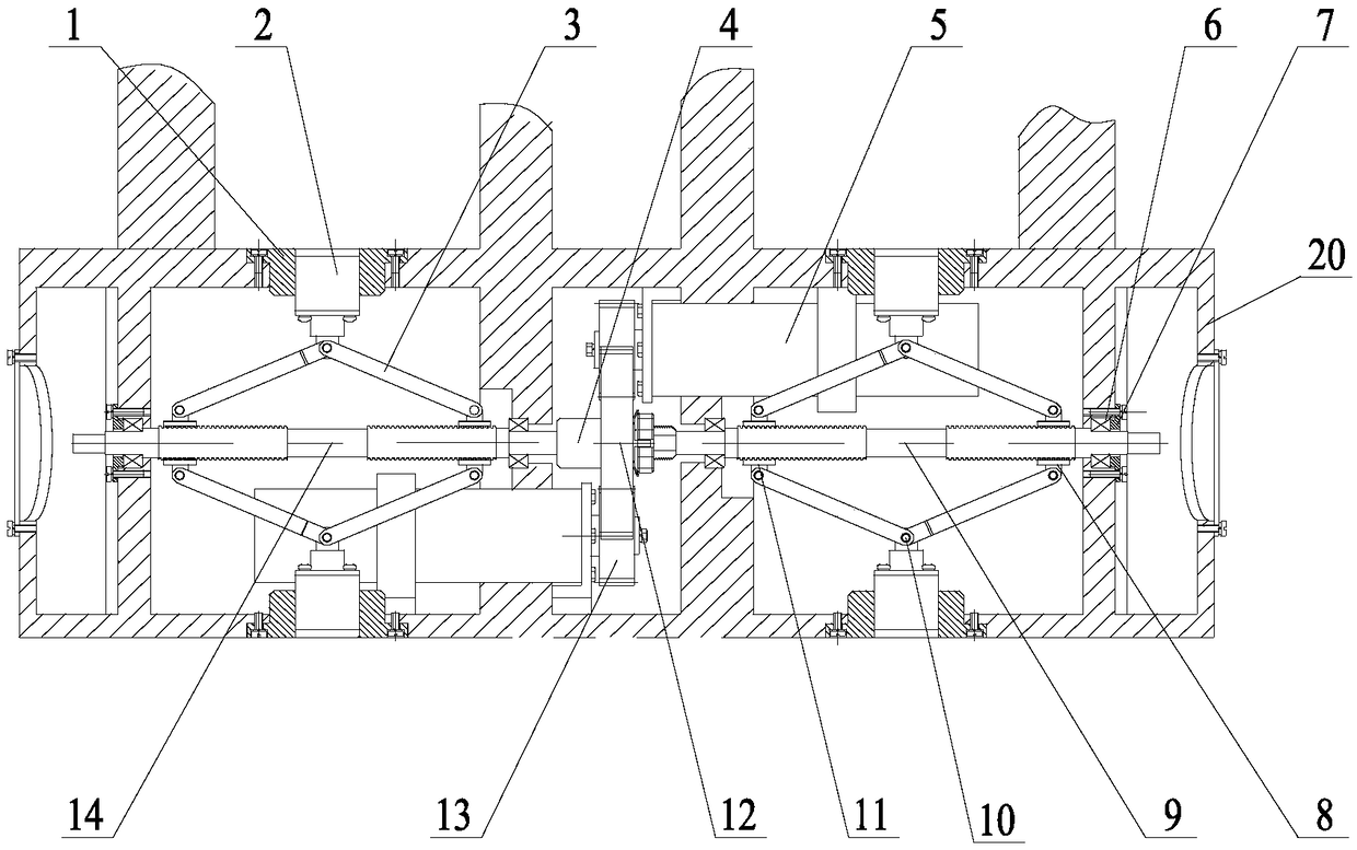
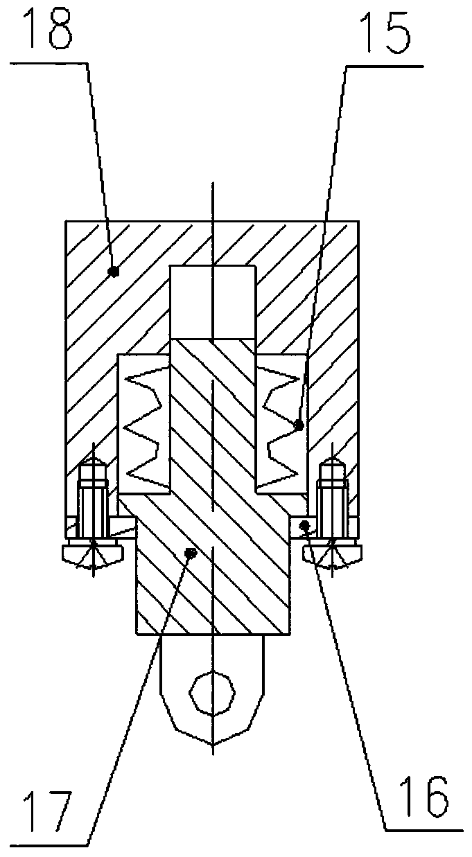
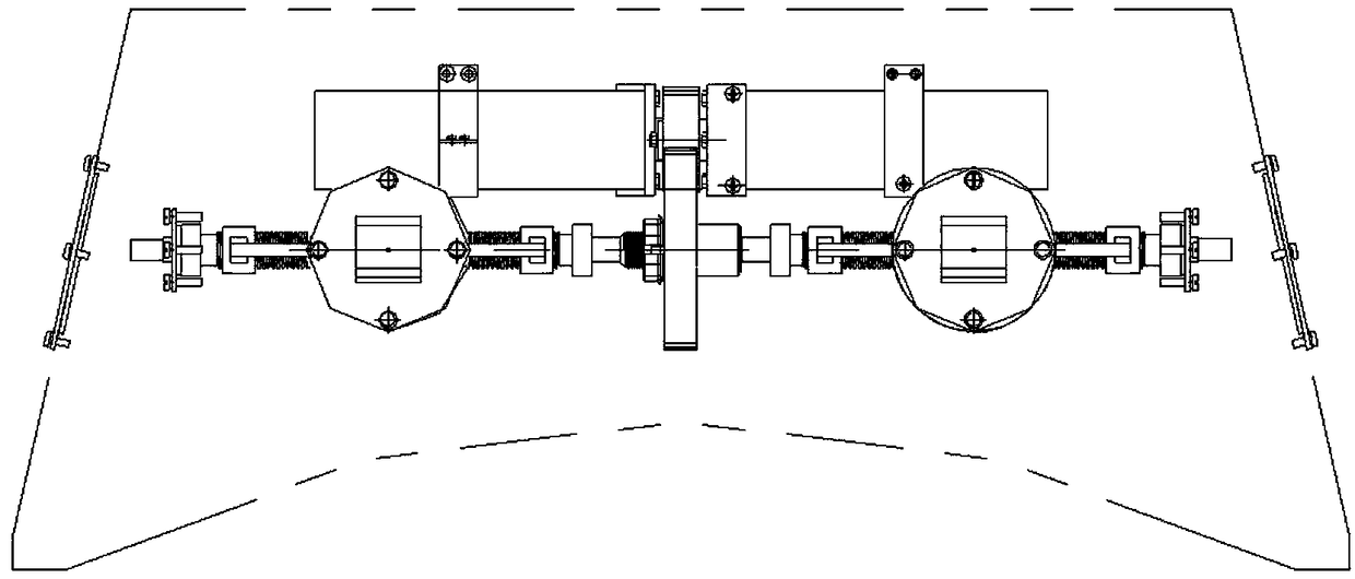
[0025] Such as Figure 1 to Figure 5 The box adaptive locking mechanism shown includes a transmission link 3, an air motor 5, an active tooth 13, and a support stand 20; the air motor 5 is fixed inside the support stand 20, and the air motor 5 drives The tooth 13 drives a screw to rotate, the screw is covered with a nut, one end of the transmission connecting rod 3 is hinged on the lug of the nut, the other end of the transmission connecting rod 3 is hinged on the bottom of the locking pin combination 2, and the locking pin combination 2 is set In the outer wall hole of the support stand 20.

[0026] The number of the air motors 5 is two, and the driving teeth 13 on the two air motors 5 are engaged with the transmission driven teeth 12, and the driven teeth 12 drive the screw to rotate.

[0027] There are two screw rods, namely t...


PUM


Abstract

The invention provides a self-adaptive locking mechanism for a box body. The self-adaptive locking mechanism comprises transmission connecting rods, pneumatic motors, driving teeth and a support rack.The pneumatic motors are fixed inside the support rack. The pneumatic motors drive screw rods to rotate through the driving teeth. Each screw rod is sleeved with nuts. One ends of the transmission connecting rods are hinged to support lugs of the corresponding nuts, and the other ends of the transmission connecting rods are hinged to the bottom of a locking pin combination. The locking pin combination is arranged in an outer wall hole of the support rack. The self-adaptive locking mechanism has the beneficial effects of small size, reasonable structural distribution and capability of being installed in a compact space with more shielding objects, has little influence on the original structure of an installation platform and requires few reprocessing procedures and has low difficulty and low installation difficulty for installing the locking mechanism; and four locking pins in the mechanism can move synchronously, and each locking pin shaft can automatically fill the axial clearance with a pin hole of the locked box body, and the axial locking force output by the mechanism is larger.

Description

technical field [0001] The invention relates to a box self-adaptive locking mechanism. Background technique [0002] According to the research and development needs of a certain equipment, it is necessary to design a locking mechanism to complete the locking or unlocking of a certain box. There are many kinds of box locking mechanisms currently available, but the structure requires a large installation space and cannot adapt to the box. The axial position deviation of the pin hole leads to the gap cannot be eliminated. [0003] For the above problems, the following difficulties should be solved: [0004] a) The structural size of the locking mechanism: the locking mechanism is installed in the inner cavity of the arc-shaped bracket of the support platform, which is limited by the space size of the inner cavity of the arc-shaped bracket, in order to meet the requirements of the axial telescopic stroke of the locking pin , it is often necessary to design a special mechanism ...

Claims


Application Information

Patent Timeline
Patent Type & Authority Applications(China)
IPC IPC(8): E05C1/12B65D55/02
CPCE05C1/12B65D55/02
Inventor 高翼邵泽亮赵银
Owner GUIZHOU AEROSPACE TIANMA ELECTRICAL TECH
Why Eureka
Try Eureka