Scene-based two-point non-uniform correction method

A non-uniformity correction and scene technology, applied in the field of infrared focal plane imaging, can solve the problems of high complexity and low correction accuracy, and achieve the effects of reasonable assumptions, improved image quality, and convenient engineering implementation

Inactive Publication Date: 2019-02-12
ZHEJIANG UNIVERSITY OF MEDIA AND COMMUNICATIONS
View PDF3 Cites 2 Cited by
  • Summary
  • Abstract
  • Description
  • Claims
  • Application Information

AI Technical Summary

Problems solved by technology

[0005] In order to solve the problems of low correction accuracy and high complexity in existing non-uniformity correction methods, the present invention provides a scene-based two-point non-uniformity correction method with high correction precision but simple and reliable implementation process

Method used


Image

  • Scene-based two-point non-uniform correction method
  • Scene-based two-point non-uniform correction method
  • Scene-based two-point non-uniform correction method

Examples


specific Embodiment approach 1

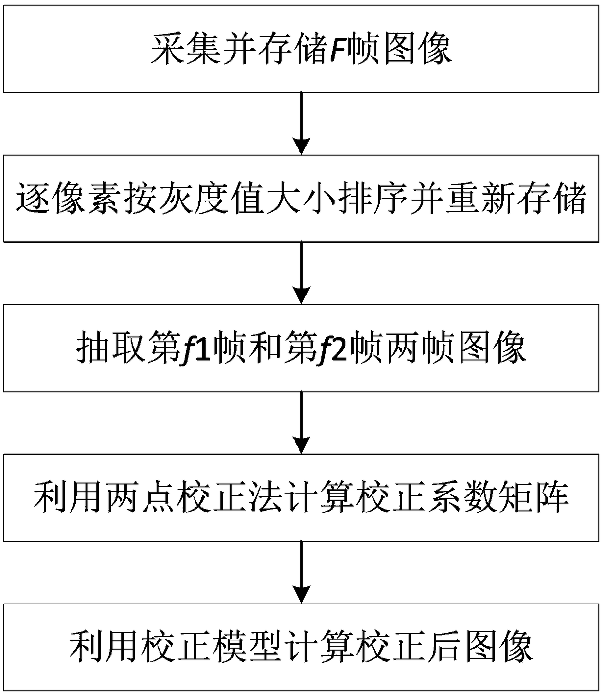
[0022] Specific implementation mode 1. Combination figure 1 Describe this embodiment, a scene-based two-point non-uniformity correction method, the method is implemented by the following steps:

[0023] Step 1. Maintain relative motion between the scene to be photographed and the LWIR detector, and collect and store F frames of the original image; relative motion between the scene to be photographed and the LWIR detector in any direction is acceptable, and there are many ways to generate relative motion: (1) It can be achieved by changing the azimuth, pitch or yaw angle, etc., and the movement speed is arbitrary; (2) Typically, for aerial cameras, the carrier aircraft can be controlled without changing the azimuth, pitch or yaw angle. Relative motion can be generated during flight.

[0024] Step 2, sorting the gray value of the collected F frame original image pixel by pixel, and storing the sorted F frame image;

[0025] Step 3. Randomly select the fth 1 frame and f 2 Fra...

specific Embodiment approach 2

[0049] Specific embodiment two, combine Figure 1 to Figure 9 This embodiment is described. In this embodiment, the scene-based two-point non-uniformity correction method described in Embodiment 1 is applied to a prototype. The principle prototype includes a cooled long-wave infrared detector produced by Sofradir and an optical lens with a focal length of 38mm. Among them, the resolution of the long-wave infrared detector is 320×256, the number of sampling bits is 14 bits, and the response band is 7.7-11.3 μm.

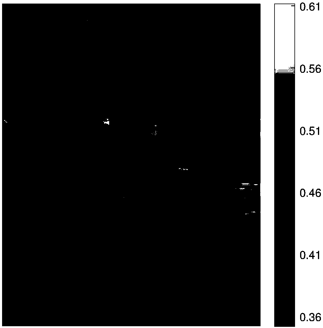
[0050] First, image the ground scene, continuously change the azimuth angle of the prototype at a speed of 5o / s, collect and store 1000 frames of original infrared images. Among them, the original image of the 200th frame is as figure 2 shown.

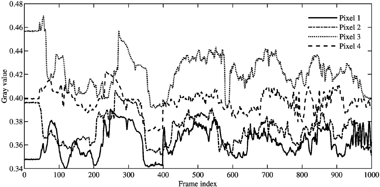
[0051] Second, sort by the gray value size pixel by pixel. Without loss of generality, four pixels are selected to analyze the algorithm principle and calculation process. The four pixels are (50, 240), (70, 220), (90, 20...


PUM


Abstract

The invention discloses a scene-based two-point non-uniform correction method, and belongs to the field of infrared focal plane imaging. By the scene-based two-point non-uniform correction method, theproblems of low correction accuracy and high complexity of an existing non-uniform correction method are solved. The scene-based two-point non-uniform correction method comprises the steps of firstly, acquiring and storing an F-frame original image; secondly, sequencing gray scale values of pixels according to sizes, and storing frame images after sequencing; thirdly, extracting a f1 frame imageand a f2 frame image; and finally, solving a correction coefficient matrix by a two-point correction method, and calculating the corrected image according to the solved correction coefficient matrix.According to the scene-based two-point non-uniform correction method, the correction coefficient does not needed to be storage in advance, the normal imaging process is not needed to be interrupted, and the problem of drift of radiation response with time is solved. The scene-based two-point non-uniform correction method has the advantages of high correction accuracy, high robustness, low time andspace complexity and wide application prospect.

Description

technical field [0001] The invention belongs to the field of infrared focal plane imaging, and in particular relates to a scene-based two-point non-uniformity correction method. Background technique [0002] The long-wave infrared detector is an important part of the infrared seeker and infrared early warning system. It has the advantages of high precision, strong anti-interference, good concealment and high cost-effectiveness, and can realize target detection, identification, tracking and positioning applications. Affected by factors such as manufacturing materials and impurities, manufacturing process, drive circuit, optical system and working environment, infrared images are often disturbed by serious non-uniform noise. The existence of non-uniform noise reduces the image resolution, seriously affects the image quality, and reduces the performance index of the infrared system. Therefore, it is necessary to study a high-precision non-uniformity correction method. [0003...

Claims


Application Information

Patent Timeline
Patent Type & Authority Applications(China)
IPC IPC(8): G01J5/00
CPCG01J5/00G01J5/80
Inventor 穆绍硕姜燕冰张解放
Owner ZHEJIANG UNIVERSITY OF MEDIA AND COMMUNICATIONS
Why Eureka
Try Eureka