An Ultrasonic Flaw Detection System for Pipelines

An ultrasonic and pipeline technology, used in the analysis of solids using sonic/ultrasonic/infrasonic waves, material analysis using sonic/ultrasonic/infrasonic waves, instruments, etc. Effect

Active Publication Date: 2021-01-15
孙中
View PDF15 Cites 0 Cited by
  • Summary
  • Abstract
  • Description
  • Claims
  • Application Information

AI Technical Summary

Problems solved by technology

[0002] Ultrasonic flaw detection is a method for inspecting parts defects by using ultrasonic energy to penetrate deep into the metal material and pass from one section to another section, reflecting at the edge of the interface to inspect parts defects. Inside the metal, when a defect and the bottom surface of the part are encountered, reflected waves will be generated respectively, and a pulse waveform will be formed on the fluorescent screen. The location and size of the defect can be judged according to these pulse waveforms. Ultrasonic waves have various wave modes when propagating in the medium, which is the most commonly used in inspection. The main ones are longitudinal waves, transverse waves, surface waves and plate waves. The longitudinal waves can be used to detect inclusions, cracks, shrinkage tubes, white spots, Defects such as delamination; use shear waves to detect circumferential and axial cracks, scratches, pores in welds, slag inclusions, cracks, incomplete penetration and other defects in pipes; use surface waves to detect defects on castings with simple shapes Surface defects; use plate waves to detect defects in thin plates. After the pipeline is laid, it is necessary to use an ultrasonic flaw detector for flaw detection. In the prior art, most of the flaw detection is done by hand-held ultrasonic flaw detectors. It is time-consuming and labor-intensive to complete the flaw detection of the pipeline manually, so we propose an ultrasonic flaw detection system for pipelines to solve the above problems

Method used


Image

  • An Ultrasonic Flaw Detection System for Pipelines
  • An Ultrasonic Flaw Detection System for Pipelines
  • An Ultrasonic Flaw Detection System for Pipelines

Examples


Embodiment

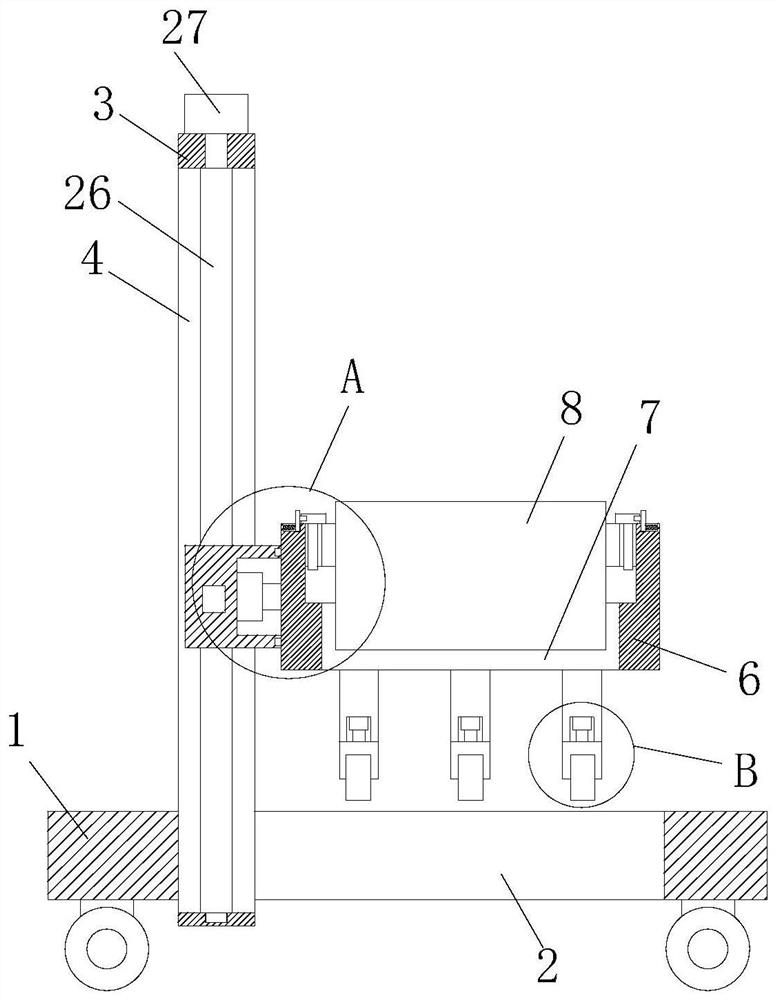
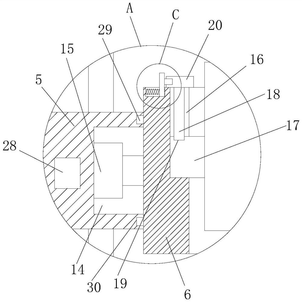
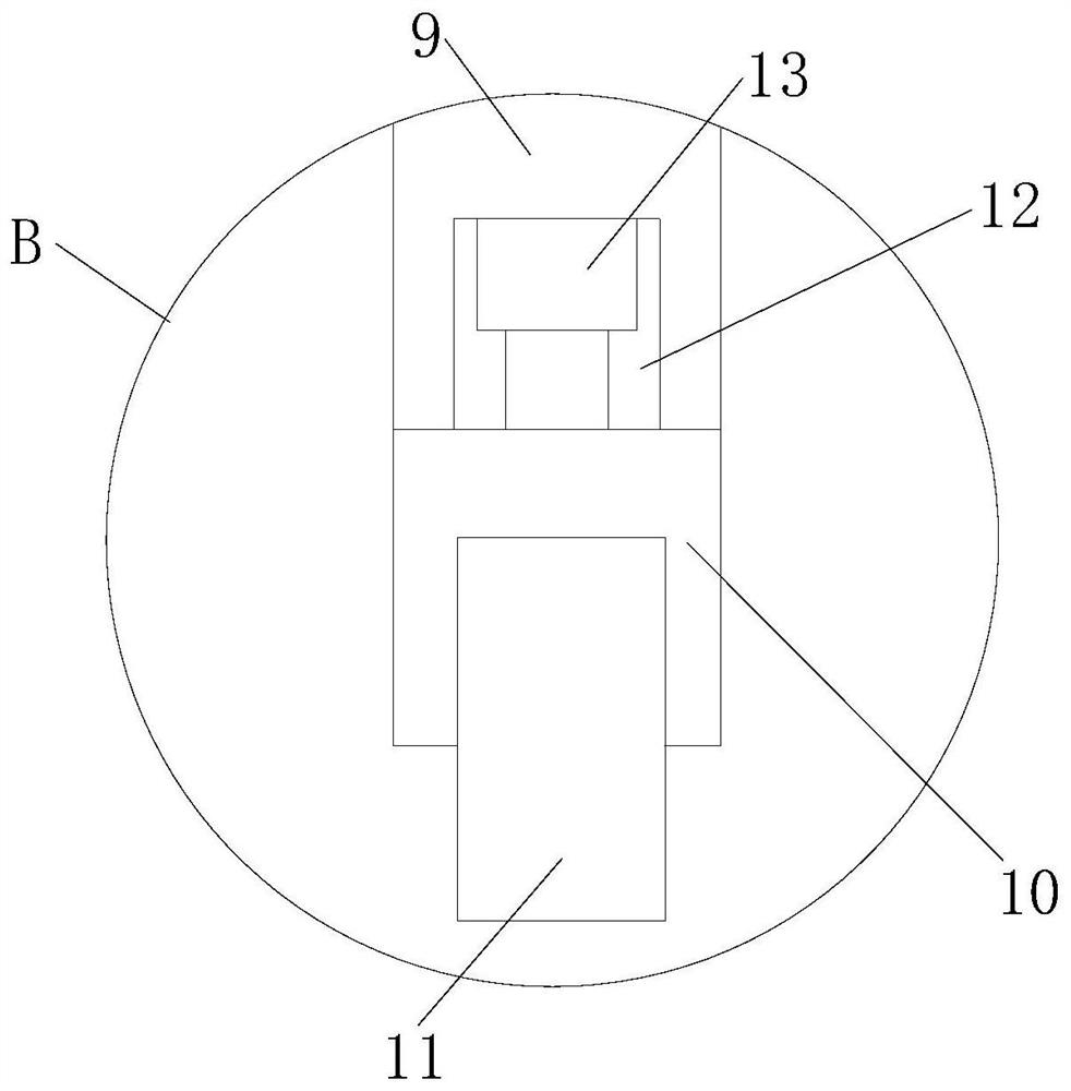
[0027] refer to Figure 1-5In this embodiment, an ultrasonic flaw detection system for pipelines is proposed, including a base 1, a through hole 2 is opened on the base 1, a vertical plate 3 is fixedly installed on the inner wall of one side of the through hole 2, and a vertical plate 3 is set on the vertical plate 3. There is a sliding hole 4, and a bearing block 5 is slidably installed in the sliding hole 4. One side of the bearing block 5 extends to the outside of the vertical plate 3 and is fixedly installed with a mounting seat 6. The mounting seat 6 is located above the base 1. On the mounting seat 6 An installation hole 7 is opened, and an ultrasonic flaw detector 8 is installed in the installation hole 7. A plurality of installation blocks 9 are fixedly installed on the bottom of the installation seat 6, and a push block 10 is installed on the bottom of the installation block 9. One side of the push block 10 is installed with Probe 11, the bottom of a plurality of moun...


PUM


Abstract

The invention discloses an ultrasonic flaw detection system used for a pipeline. The system includes a base seat. A through hole is formed on the base seat. Riser plates are fixedly mounted on an inner wall of one side of the through hole. Sliding holes are formed on the riser plates. A carrier block is mounted in the sliding holes in a sliding manner. One side of the carrier block extends to theoutside of a riser plate. A mounting seat is fixedly mounted on the one side of the carrier block, and is located above the base seat. A mounting hole is formed on the mounting seat. An ultrasonic flaw detector is mounted in the mounting hole. A plurality of mounting blocks are fixedly mounted at the bottom of the mounting seat. A pushing block is mounted at the bottom of each mounting block. A probe is mounted on one side of the pushing block. According to the system, adjustment on a position of the probe is facilitated, flipping of the probe is also facilitated, flaw detection on pipelines which are laid underground and erected in the air is facilitated, time and effort are saved, disassembly on the ultrasonic flaw detector is facilitated at the same time, maintenance is facilitated whena fault occurs, a structure is simple, and use is convenient.

Description

technical field [0001] The invention relates to the technical field of ultrasonic flaw detection, in particular to an ultrasonic flaw detection system for pipelines. Background technique [0002] Ultrasonic flaw detection is a method for inspecting parts defects by using ultrasonic energy to penetrate deep into the metal material and pass from one section to another section, reflecting at the edge of the interface to inspect parts defects. Inside the metal, when a defect and the bottom surface of the part are encountered, reflected waves will be generated respectively, and a pulse waveform will be formed on the fluorescent screen. The location and size of the defect can be judged according to these pulse waveforms. Ultrasonic waves have various wave modes when propagating in the medium, which is the most commonly used in inspection. The main ones are longitudinal waves, transverse waves, surface waves and plate waves. The longitudinal waves can be used to detect inclusions, ...

Claims


Application Information

Patent Timeline
Patent Type & Authority Patents(China)
IPC IPC(8): G01N29/04G01N29/22
CPCG01N29/04G01N29/22G01N2291/023G01N2291/0234
Inventor 罗峰
Owner 孙中
Why Eureka
Try Eureka