A catadioptric infrared zoom optical system

An optical system and zoom technology, applied in the optical field, can solve the problems of large diameter and volume of the optical system, long focal length of the optical system, unable to achieve a large field of view, etc., achieve high-quality imaging, solve the zoom problem, and shorten the optical length. Effect

Active Publication Date: 2020-11-24
LUOYANG INST OF ELECTRO OPTICAL EQUIP OF AVIC
View PDF7 Cites 0 Cited by
  • Summary
  • Abstract
  • Description
  • Claims
  • Application Information

AI Technical Summary

Problems solved by technology

[0004] The optical system of the current infrared zoom thermal imager is generally designed with a transmission optical system, which can meet the general application requirements, but for ultra-long-distance target detection, the focal length of the optical system is required to be very long, which causes the optical system The caliber and volume are too large, and the manufacturing cost is significantly increased
If the optical system is designed with a reflective optical system, although it can achieve a long focal length, the inherent disadvantage of the reflective optical configuration is that the field of view is small and cannot achieve a large field of view

Method used


Image

  • A catadioptric infrared zoom optical system
  • A catadioptric infrared zoom optical system
  • A catadioptric infrared zoom optical system

Examples


Embodiment

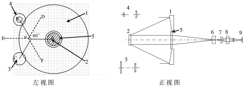
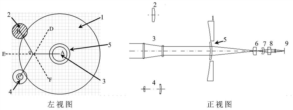
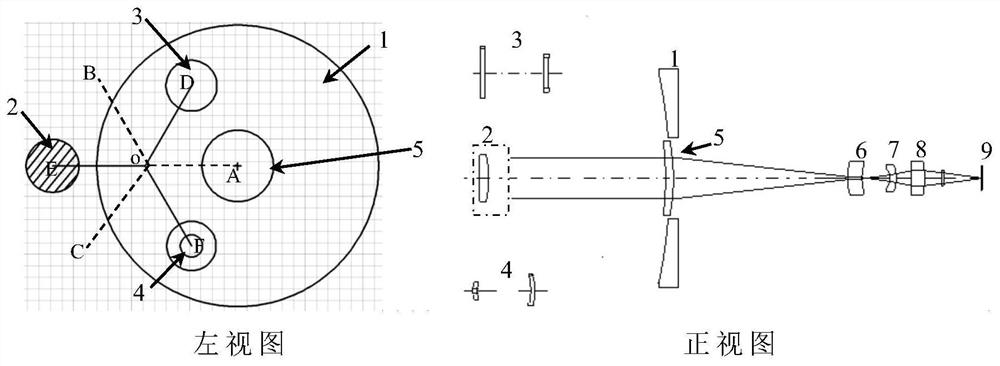
[0037] The schematic diagram of the optical path is a configuration realization principle diagram of a catadioptric infrared zoom optical system.

[0038] The optical system system includes Galileo telescopic hollow reflective objective lens 1, Galileo telescopic reflective eyepiece 2, small field of view zoom lens group 3, large field of view zoom lens group 4, lens 5, lens 6, lens 7, lens 8 and detection Device 9.

[0039] The specific optical parameters are shown in the table below.

[0040] Ultra-small field of view optical path optical parameter table (unit: mm)

[0041]

[0042]

[0043] Small field of view optical path optical parameter table (unit: mm)

[0044]

[0045]

[0046]

[0047] Optical parameter table of optical path in medium field of view (unit: mm)

[0048]

[0049]

[0050]Large field of view optical path optical parameter table (unit: mm)

[0051]

[0052]

[0053]

[0054] The aspheric equation is:

[0055]

[0056]...


PUM


Abstract

The invention relates to a refraction and reflection type infrared varifocal optical system. The configuration of the optical system is determined based on reflection varifocal principle and paraxialoptical system theoretical calculation analysis, and the aberration of the optical system is corrected through optical structure parameter optimization, aberration balance and the adoption of specialfacial forms such as aspheric surfaces and diffraction surfaces, so that the image quality reaches the optimal. According to the optical system, based on the combination with optical reflection principle and refraction principle, switching of extra-small fields, small fields, medium fields and large fields for the optical system is realized through switching of different zooms of lens assemblies,and high-quality imaging can be maintained. The optical system solves the zoom problem of overlong focal length multi-field, the optical length is shortened, the space volume of the system is saved, and the manufacturing cost of the optical system is reduced.

Description

technical field [0001] The invention belongs to the optical technology and relates to a catadioptric infrared variable focal length optical system. Background technique [0002] In order to obtain images of different sizes on the image plane of a fixed-focus infrared camera, the distance between the target object and the lens must be changed or a lens with a different focal length must be replaced. The zoom thermal imager can change the focal length of the optical system. Therefore, target images of different sizes can be obtained on the image plane, which is very beneficial for photoelectric observation and monitoring. [0003] Depending on the distance of the target to be observed, the photoelectric observation and monitoring system usually requires the optical system to have multiple focal lengths, which are used for detection, identification and large-scale monitoring of targets at different distances. [0004] The optical system of the current infrared zoom thermal ima...

Claims


Application Information

Patent Timeline
Patent Type & Authority Patents(China)
IPC IPC(8): G02B15/04G02B15/12
CPCG02B15/04G02B15/12
Inventor 刘红霞张良毕野彪吴晓鸣
Owner LUOYANG INST OF ELECTRO OPTICAL EQUIP OF AVIC
Why Eureka
Try Eureka