Power jointing clamp

A terminal clip and power technology, applied in the direction of conductive connection, electrical component connection, connection, etc., can solve the problems of cumbersome use, limited application scope, inconvenient overlapping, etc., and achieve the effect of increasing friction and preventing fingers from slipping.

Active Publication Date: 2019-02-12
STATE GRID CORP OF CHINA +2
View PDF11 Cites 3 Cited by
  • Summary
  • Abstract
  • Description
  • Claims
  • Application Information

AI Technical Summary

Problems solved by technology

The clamp is easy to remove and save, but it is still cumbersome to use, especially inconve

Method used


Image

  • Power jointing clamp
  • Power jointing clamp
  • Power jointing clamp

Examples


Embodiment Construction

[0026] The standard parts used in the present invention can be purchased from the market, and the special-shaped parts can be customized according to the instructions and the accompanying drawings. The specific connection methods of each part adopt mature bolts, rivets, welding in the prior art , pasting and other conventional means, no longer described in detail here.

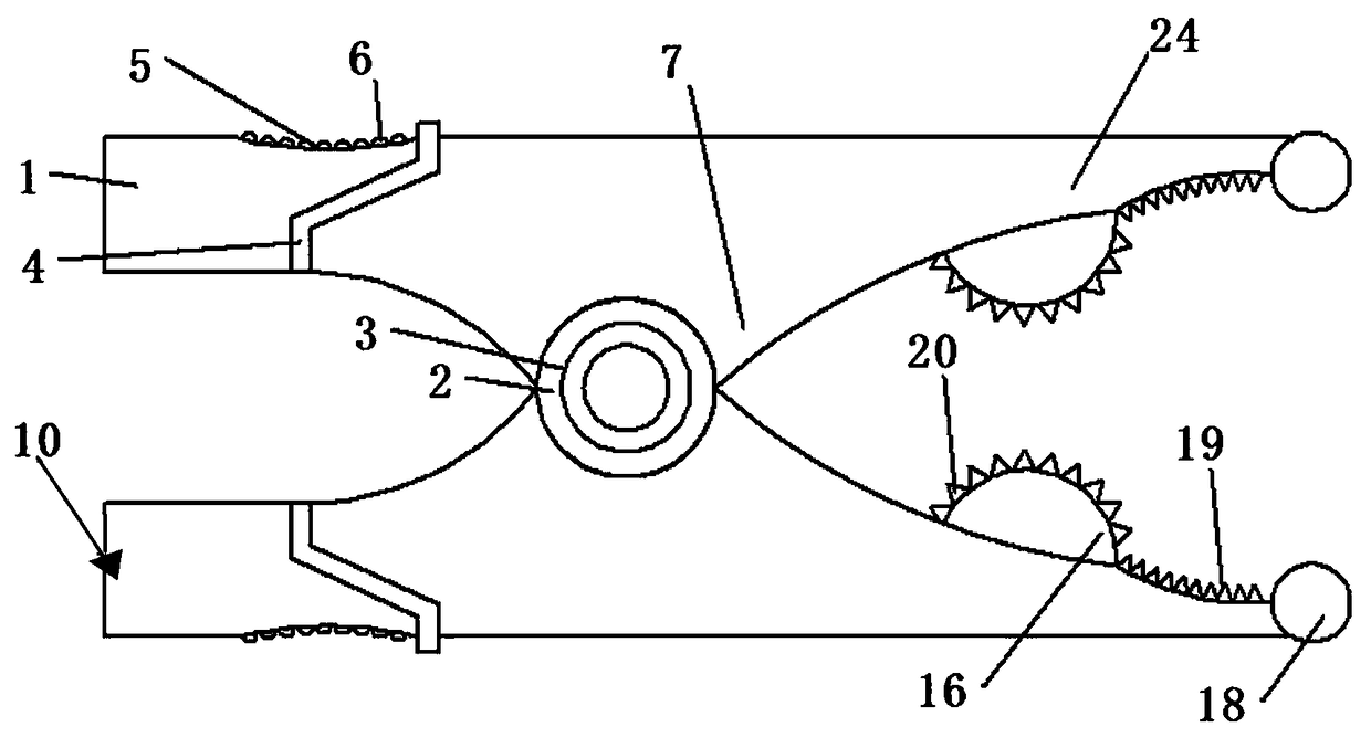
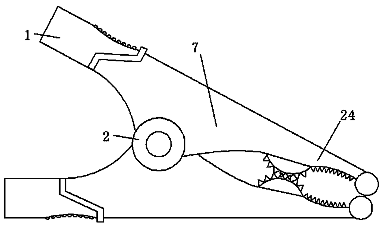
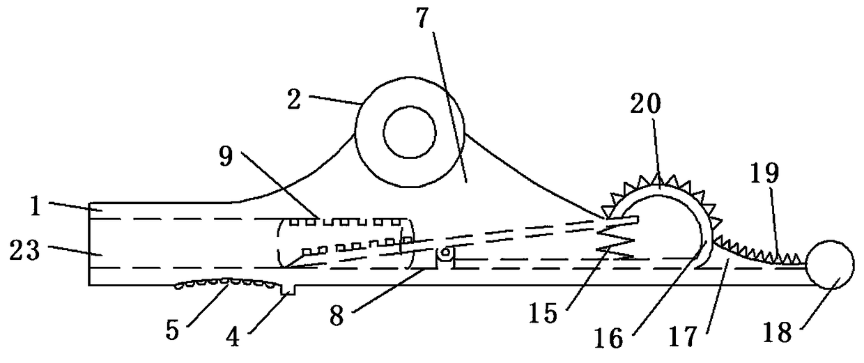
[0027] refer to Figure 1-4 , the present invention provides a power connection clip, which includes two mutually hinged insulating half clips, a metal frame 8 fixedly arranged inside the insulating half clips, and a metal sleeve fixedly arranged on the rear side of the metal frame 8 Pipe 9, the insulating half clamp body includes a front clamp body 24 located at the front side, a connecting part 7 located in the middle and a rear clamp body 1 at the rear side which are integrally arranged. The connecting part 7 is articulated through the rotating shaft 2, so The rotating shaft 2 is provided with a torsion sp...


PUM


Abstract

The invention provides a power jointing clamp, which comprises two insulating half clamp bodies hinged to each other, a metal framework fixedly disposed on the inner sides of the insulating half clampbodies, and a metal sleeve fixedly disposed on the rear side of the metal framework, wherein the insulating half clamp bodies comprise front clamp bodies integrally located on the front sides, middleconnecting parts, and rear clamping bodies on the rear sides; the connecting parts are movably hinged by a rotating shaft, and the front side of the metal framework is fixedly provided with a third metal sheet; first metal teeth are fixedly arranged on the inner side of the third metal sheet; the inner side of the metal framework is fixedly connected with a second metal sheet; the front side of the second metal sheet is fixedly provided with an arc-shaped metal sheet; the convex surface of the arc-shaped metal sheet is inward; second metal teeth are fixedly arranged on the arc-shaped metal sheet; and a spring is arranged between the first metal sheet and the second metal sheet. The power jointing clamp has the characteristics of simplicity and practicability and can quickly lap two cables.

Description

technical field [0001] The invention relates to the field of safety protection for low-voltage live work, in particular to a power connection clip. Background technique [0002] Our country is a country that consumes a lot of energy. As a kind of energy, electricity is widely used in our country. Substation is an indispensable link in the power transmission process, and operation and maintenance personnel working in substations often use terminal clips. Chinese invention patent CN 203311945 U discloses a terminal clamp. The terminal clamp of this structure includes a rigid frame and an insulating layer covering the surface of the rigid frame. The terminal clip is convenient for removal and storage, but it is still cumbersome to use, especially inconvenient when quickly splicing multiple external cables, thus limiting its scope of application. Contents of the invention [0003] The technical problem to be solved by the present invention is to provide a power connection c...

Claims


Application Information

Patent Timeline
IPC IPC(8): H01R11/05H01R11/01H01R4/48
CPCH01R4/4809H01R4/4863H01R4/4872H01R11/01H01R11/05
Inventor 杜鹏
Owner STATE GRID CORP OF CHINA
Why Eureka
Try Eureka