Battery power supply circuit

A power supply circuit and battery technology, which is applied in the direction of battery disconnection circuit, battery circuit device, load supply circuit, etc., can solve the problem that the battery cannot achieve zero power consumption, etc.

Pending Publication Date: 2019-02-12
中山市奥东电子科技有限公司
View PDF0 Cites 2 Cited by
  • Summary
  • Abstract
  • Description
  • Claims
  • Application Information

AI Technical Summary

Problems solved by technology

[0005] The purpose of the present invention is to provide a battery power supply circuit to solve the problem in

Method used


Image

  • Battery power supply circuit

Examples


no. 1 example

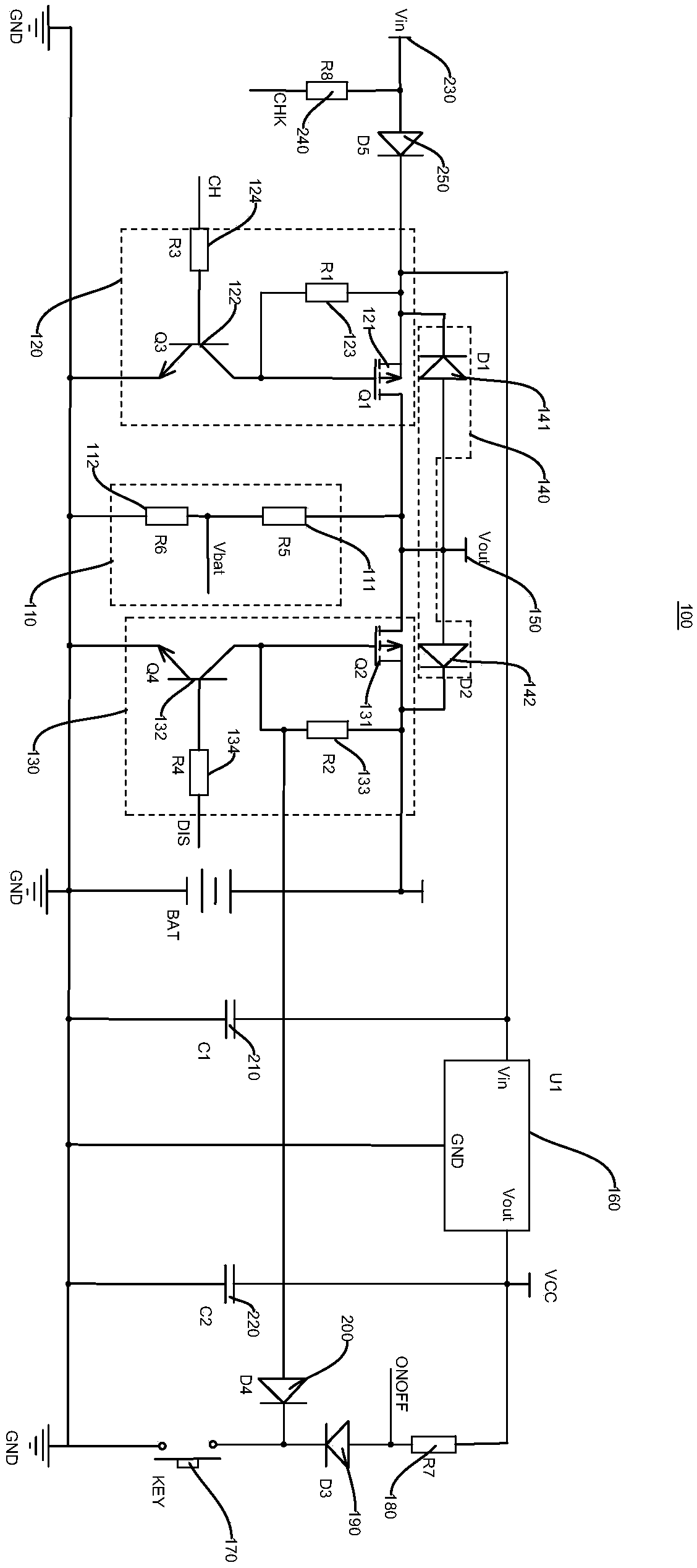
[0029] see figure 1, the embodiment of the present invention provides a battery power supply circuit, the battery power supply circuit includes a main control chip, a voltage division detection circuit, a first switch component 120, a second switch component 130, a logic component 140 and a power supply output terminal 150, the main control The chip is electrically connected to the divided voltage detection circuit, the first switch assembly 120 and the second switch assembly 130 respectively, and the logic assembly 140 is electrically connected to the first switch assembly 120 and the second switch assembly respectively, and the logic assembly 140 is arranged with the first switch assembly Between 120 and the second switch assembly 130, the power supply output terminal 150 is electrically connected to the logic assembly 140, the voltage division detection circuit, the first switch assembly 120 and the second switch assembly 130, and the second switch assembly 130 is connected ...


PUM


Abstract

The invention provides a battery power supply circuit, and relates to the technical field of battery charging and discharging. The battery power supply circuit comprises a master control chip, a voltage-dividing detection circuit, a first switch assembly, a second switch assembly, a logic assembly and a power supply output end; when the power supply circuit is in a discharging state, the second switch assembly is closed, a power supply supplies power to the external; the master control chip is used for detecting voltage information through the voltage-dividing detection circuit after being conducted, and controlling the second switch assembly to be turned off when the voltage information is lower than the preset voltage value. The power supply circuit has the advantage of realizing zero power consumption in a standby state.

Description

technical field [0001] The invention relates to the technical field of battery charging and discharging, in particular to a battery power supply circuit. Background technique [0002] At present, the battery protection chip and peripheral circuit on the market can protect the battery from overcharging and overdischarging. During the charging process of the battery, when the battery voltage reaches the protection voltage, the charging will be cut off, so as to realize the overcharging protection of the battery; During the process, when the battery voltage reaches the protection voltage, the discharge is cut off, so as to realize the over-discharge protection of the battery. [0003] However, during the over-discharge protection process, the battery protection chip still needs to take power from the battery to work in the standby state, and consumes power at the microampere level, so that the effect of truly protecting the battery cannot be achieved. [0004] How to solve the...

Claims


Application Information

Patent Timeline
IPC IPC(8): H02J7/00
CPCH02J7/00306H02J7/0031H02J7/0063
Inventor 莫如东
Owner 中山市奥东电子科技有限公司
Why Eureka
Try Eureka