
The control circuit of the power output of the driver board

A technology for controlling circuit and power output, applied in output power conversion devices, high-efficiency power electronic conversion, electrical components, etc., can solve problems such as power consumption and waste of energy, and achieve the effect of saving power consumption

Active Publication Date: 2020-08-11
QINGDAO HAIER SMART TECH R & D CO LTD +1
View PDF10 Cites 0 Cited by
  • Summary
  • Abstract
  • Description
  • Claims
  • Application Information

AI Technical Summary

Problems solved by technology

Therefore, it will cause unnecessary power consumption and waste energy

Method used


Image

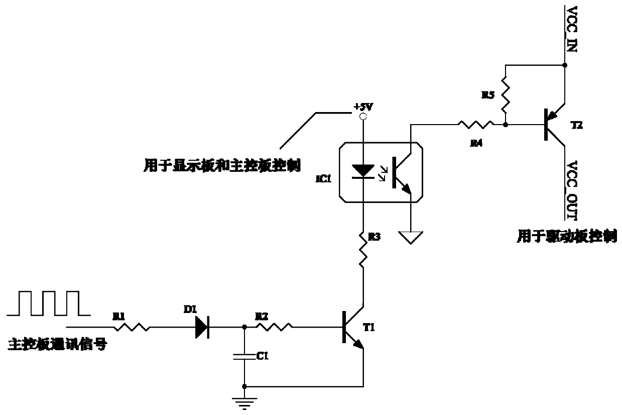
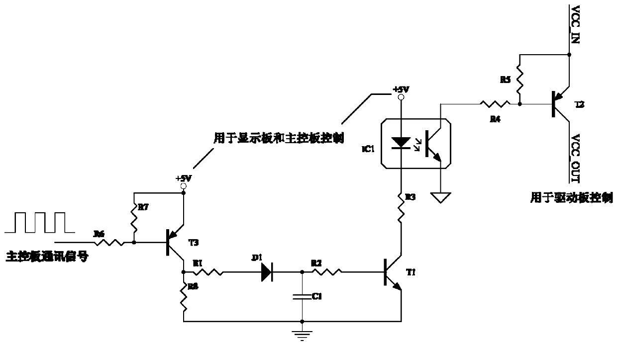
  • The control circuit of the power output of the driver board
  • The control circuit of the power output of the driver board
  • The control circuit of the power output of the driver board

Examples


Embodiment Construction

[0041] The following description and drawings illustrate specific embodiments of the invention sufficiently to enable those skilled in the art to practice them. The examples merely represent possible variations. Individual components and functions are optional unless explicitly required, and the order of operations may vary. Portions and features of some embodiments may be included in or substituted for those of other embodiments. The scope of embodiments of the present invention includes the full scope of the claims, and all available equivalents of the claims. Herein, various embodiments may be referred to individually or collectively by the term "invention", which is for convenience only and is not intended to automatically limit the scope of this application if in fact more than one invention is disclosed. A single invention or inventive concept. Herein, relational terms such as first and second etc. are used only to distinguish one entity or operation from another with...


PUM


Abstract

The invention discloses a control circuit for power output of a drive board, including: an optocoupler drive circuit, a photocoupler, and a switching power supply drive circuit, wherein the optocoupler drive circuit is connected to a pin of the main control board in the electrical equipment respectively , and the light-emitting source connection in the photocoupler is used to control the light-emitting source to emit light when receiving the drive signal output by the pin to control the drive board to enter the working state; When the signal is driven, the light emitting source is controlled to be extinguished; the switching power supply drive circuit is respectively connected with the light receiver in the photocoupler and the switching tube of the drive board power supply, and is used for when the light receiver is turned on, the The switch tube is turned on so that the drive board power supply outputs voltage, and when the light receiver is not turned on, the switch tube is turned off so that the drive board power supply does not output voltage.

Description

technical field [0001] The invention relates to the technical field of smart home appliances, in particular to a control circuit for outputting power from a drive board. Background technique [0002] At present, the frequency conversion refrigerator controller is generally divided into a display board, a main control board and a drive board. The display board is mainly used to display and set the temperature control of the refrigerator compartment; the main control board is used to detect temperature sensors, door switches, etc., and control loads such as dampers, fans, ice machines, electric heating, and valves; the drive board is mainly used for Drive the compressor according to the driving signal sent by the main control board. [0003] According to product characteristics, operating status, and external environment and other conditions, the compressor of a refrigerator is periodically turned on and off, and the average stop time of the compressor accounts for about 30% ...

Claims


Application Information

Patent Timeline
Patent Type & Authority Patents(China)
IPC IPC(8): H02M1/00H02M1/06H02M1/08
CPCH02M1/00H02M1/06H02M1/08H02M1/0032Y02B70/10
Inventor 虞朝丰宋洪强王堃许升
Owner QINGDAO HAIER SMART TECH R & D CO LTD
Learn More