an energy-saving mechanism

A technology of electromagnetic mechanism and moving iron core, applied in the direction of protection switch operation/release mechanism, etc., can solve problems such as power consumption, and achieve the effect of improved reliability, good reliability, and zero power consumption

Inactive Publication Date: 2017-01-25
JAECELE ELECTRIC
View PDF4 Cites 0 Cited by
  • Summary
  • Abstract
  • Description
  • Claims
  • Application Information

AI Technical Summary

Problems solved by technology

[0008] Therefore, the technical problem to be solved by the present invention lies in the problem that the electromagnetic mechanism used in the smart meter actuator in the prior art must be energized for a long time to cause a large amount of electric energy consumption, thereby providing a smart meter actuator. , an energy-saving mechanism that is used in conjunction with the electromagnetic mechanism and can avoid consuming a large amount of electric energy when the electromagnetic mechanism is closed

Method used


Image

  • an energy-saving mechanism
  • an energy-saving mechanism
  • an energy-saving mechanism

Examples


Embodiment 1

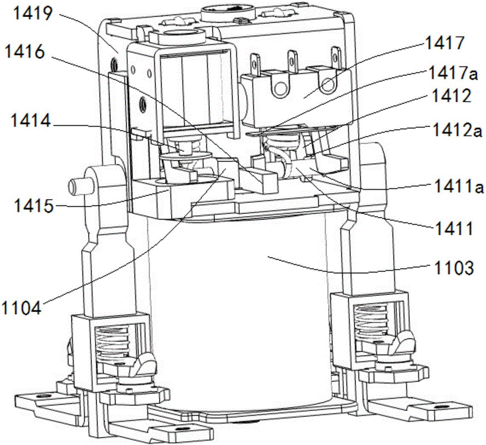
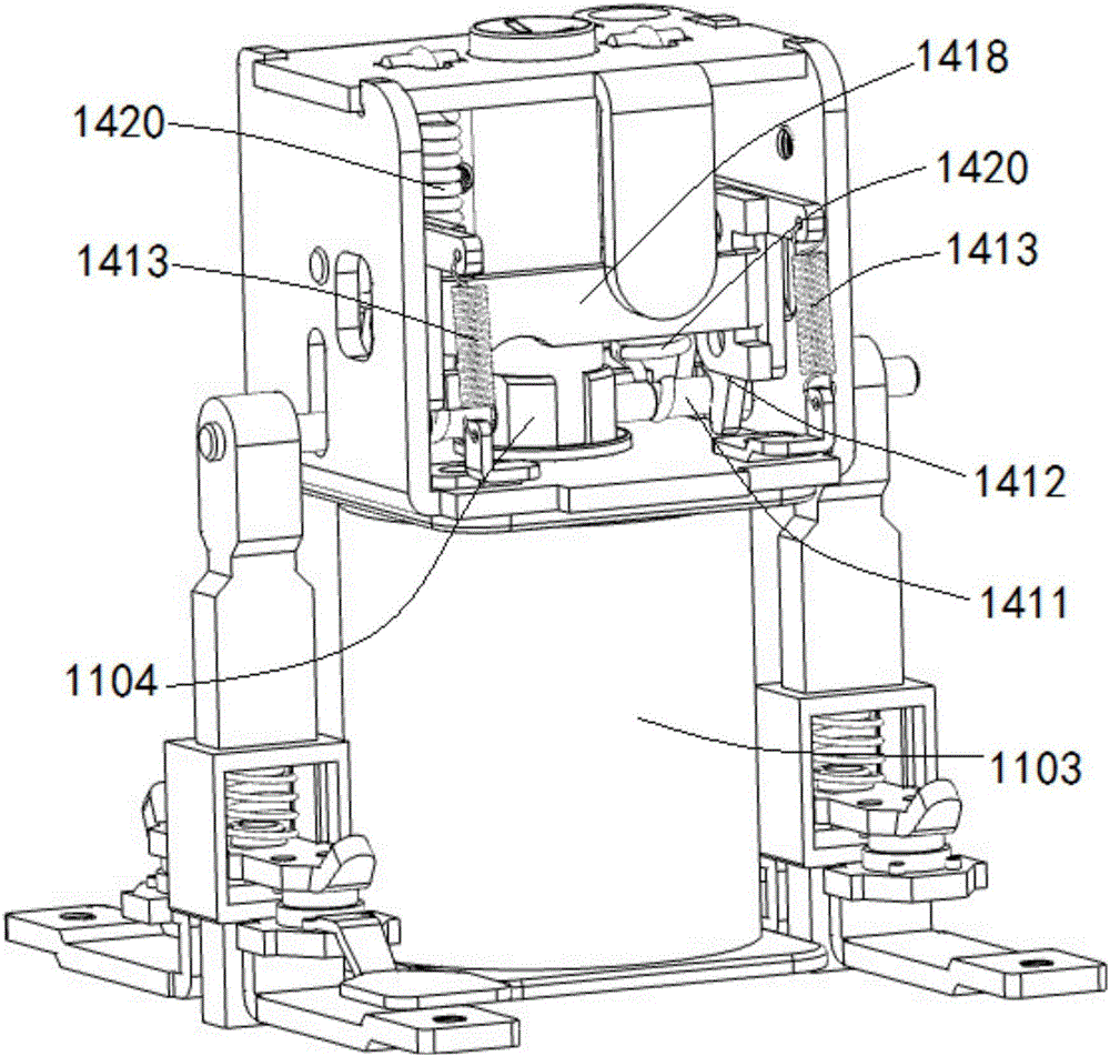
[0048] Such as Figure 1-4 Shown is a preferred embodiment of the energy-saving mechanism of the present invention. The energy-saving mechanism is used in conjunction with an electromagnetic mechanism, wherein the electromagnetic mechanism is an electromagnetic mechanism commonly used in the prior art, that is, the electromagnetic mechanism includes a reciprocating moving iron core 1104 and a coil 1103, and the moving iron core 1104 It has an initial position before the coil 1103 is energized and a pull-in position that moves from the initial position to when the coil 1103 is energized. In the existing electromagnetic mechanism, its suction position is the working position. When the electromagnetic mechanism is applied to the smart meter actuator, the pull-in position of the electromagnetic mechanism is the closing position of the actuator, and the initial position of the electromagnetic mechanism is the opening position of the actuator.

[0049] In this example, if Figure...

Embodiment 2

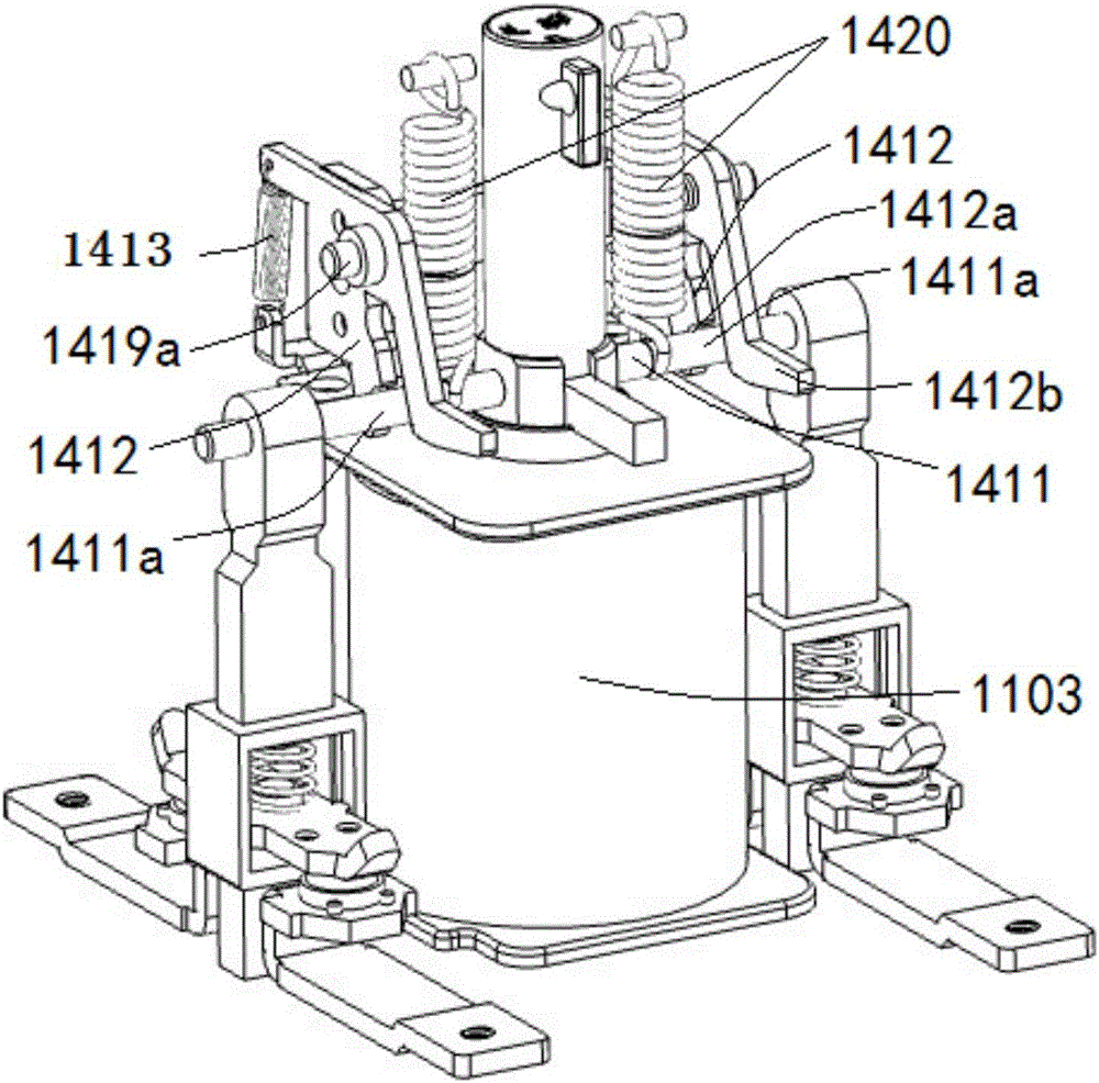
[0061]As an alternative structure of the reset member 1415 in the energy-saving mechanism in Embodiment 1, in this embodiment, the reset member 1415 is the triggered part 1412b of the locking member 1412, and the triggered part 1412b is After the tripping end 1414 is triggered, the tripping end 1414 is pushed back to the return position under the action of the biasing force of the biasing member 1403 . In this embodiment, the structure and working method of the triggered part 1412b and the biasing part 1403 are fully utilized, and the triggered part 1412b is used as a reset part. After the triggering part 1412b rotates the triggered part 1412b in a small angle along the triggering direction, the triggered part 1412b reversely rotates again under the biasing force of the biasing member, thereby pushing the tripping end 1414 back To the return position, in this implementation, there is no need to separately arrange a reset member for driving the trip end to return, which saves p...


PUM


Abstract

An energy conservation mechanism is suitable for being used in cooperation with an electromagnetic mechanism. The energy conservation mechanism comprises a lock catch unit, an energy conservation unit and a releasing unit. A movable iron core of the electromagnetic mechanism moves to the pull-in position of the movable iron core the moment a coil is powered on. A lock catch structure is formed between the lock catch unit and the movable iron core so that the movable iron core can be kept unmoved at the pull-in position. Meanwhile, the energy conservation unit controls the coil to be powered off the moment the movable iron core moves away from an initial position, so that zero power consumption is realized when the electromagnetic mechanism works, and a large amount of electricity is saved. The releasing unit can receive a releasing instruction and triggers the lock catch unit to unlock the lock catch structure, so that the movable iron core is made to return to the initial position quickly; besides, the releasing unit can return to the returning position after the releasing process to be used next time.

Description

technical field [0001] The invention relates to a smart meter actuator used in conjunction with a smart meter, in particular to an energy-saving mechanism used in conjunction with an electromagnetic mechanism in the smart meter actuator, and belongs to the technical field of low-voltage electrical accessories. Background technique [0002] The smart meter is the smart terminal of the smart grid. It is no longer a meter in the traditional sense. In addition to the basic power consumption measurement function of the traditional meter, the smart meter also has two-way multiple tariffs in order to adapt to the use of smart grid and new energy. Intelligent functions such as metering function, user terminal control function, two-way data communication function of multiple data transmission modes, and anti-theft function, smart meters represent the development direction of future energy-saving smart grid end-user intelligent terminals. [0003] Smart meters are mostly used in conju...

Claims


Application Information

Patent Timeline
Patent Type & Authority Patents(China)
IPC IPC(8): H01H71/10H01H71/24H01H71/68
Inventor 彭全昌刘永华
Owner JAECELE ELECTRIC
Why Eureka
Try Eureka