
Switch power source of output ripple suppression circuit topological structure

A suppression circuit and switching power supply technology, applied in the direction of output power conversion device, DC power input conversion to DC power output, electrical components, etc., can solve the problem of large equipment size, low ripple, application restrictions on switching power supply output ripple, etc. problems, to achieve the effect of stable control ripple

Pending Publication Date: 2019-02-12
江苏特智智能装备股份有限公司
View PDF8 Cites 1 Cited by
  • Summary
  • Abstract
  • Description
  • Claims
  • Application Information

AI Technical Summary

Problems solved by technology

[0002] At present, switching power supply is widely used in various industrial fields due to its small size and high efficiency. However, in some high-precision and high-precision applications, the high output ripple of switching power supply limits its application. Conventional power frequency linear rectification The power supply ripple is low, but the equipment is large in size and low in efficiency. It does not have the advantages of switching power supply, so a switching power supply with low output ripple is needed to make up for its application.

Method used


Image

  • Switch power source of output ripple suppression circuit topological structure
  • Switch power source of output ripple suppression circuit topological structure

Examples


Embodiment Construction

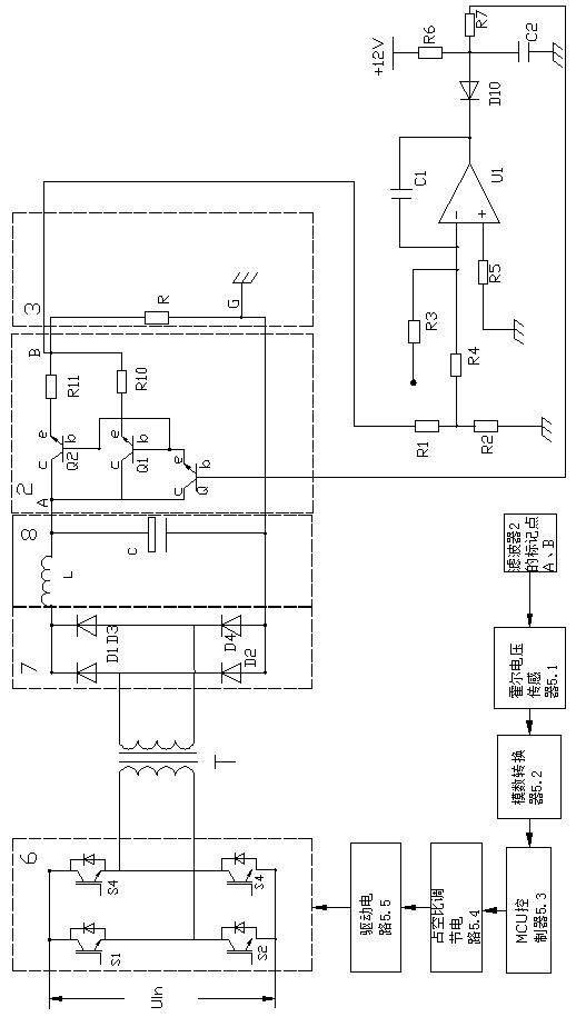
[0018] Such as figure 1 , 2 As mentioned above, the present invention includes a power supply circuit 1 , a filter 2 , an output circuit 3 , a first control loop 4 , and a second control loop 5 , and the filter 1 is connected between the power supply circuit 1 and the output circuit 3 .

[0019] The power supply circuit 1 includes a transformer T, the input end of the transformer T is connected to a full bridge circuit 6, the input end of the full bridge circuit 6 is connected to the input power supply Uin, the output end of the transformer T is connected to a rectifier bridge 7, and the output end of the rectifier bridge 7 is connected to a filter circuit 8.

[0020] The full bridge circuit 6 includes a first switch S1, a second switch S2, a third switch S3 and a fourth switch S4, and the first switch S1, the second switch S2, the third switch S3 and the fourth switch S4 can use MOS tubes or IGBTs module, the positive pole of the input power supply Uin is connected to one e...


PUM


Abstract

The invention relates to the technical field of power electronic conversion, in particular to a switch power source of an output ripple suppression circuit topological structure. The switch power source comprises a power circuit and an output circuit connected to an output end of the power circuit. The switch power source is characterized by further comprising a filter, a first control loop and asecond control loop, the filter is connected between the power circuit and the output circuit, and an input end of the first control loop is connected with the output circuit while an output end is connected with the filter; the first control loop is used for acquiring voltage of the output circuit, comparing with a set value and taking an obtained error value as a reference to control a stable value of the filter; the second control loop is used for acquiring voltage at two ends of the filter to take as a reference, comparing with a set value and controlling output voltage of the power circuit. By adding of a filter circuit to output of the switch power source and current sharing of the filter circuit, output voltage stable control and ripple suppression are realized through two-stage control loops.

Description

technical field [0001] The invention relates to the technical field of power electronic conversion, in particular to a switching power supply with an output ripple suppression circuit topology. Background technique [0002] At present, switching power supply is widely used in various industrial fields due to its small size and high efficiency. However, in some high-precision and high-precision applications, the high output ripple of switching power supply limits its application. Conventional power frequency linear rectification The power supply ripple is low, but the equipment is large in size and low in efficiency and does not have the advantages of switching power supply, so a switching power supply with low output ripple is needed to make up for its application. Contents of the invention [0003] The purpose of the present invention is to provide a switching power supply with an output ripple suppression circuit topology. By adding a first-stage filter topology to the o...

Claims


Application Information

Patent Timeline
Patent Type & Authority Applications(China)
IPC IPC(8): H02M3/335H02M1/15
CPCH02M1/15H02M3/33523
Inventor 潘小刚王海波宋文弟孙前双严松顾小军
Owner 江苏特智智能装备股份有限公司
Learn More