Chamfering device of automobile chassis supporting frame

A technology of chamfering device and automobile chassis, which is applied in boring/drilling, metal processing equipment, drilling/drilling equipment, etc. Control, reduce production labor, the effect of simple structure

Pending Publication Date: 2019-02-15
WUHU YUANSHAN MACHINERY MFG CO LTD
View PDF2 Cites 2 Cited by
  • Summary
  • Abstract
  • Description
  • Claims
  • Application Information

AI Technical Summary

Problems solved by technology

However, this kind of equipment still has the defects that the chamfering position is fixed and only a single chamfering

Method used


Image

  • Chamfering device of automobile chassis supporting frame
  • Chamfering device of automobile chassis supporting frame
  • Chamfering device of automobile chassis supporting frame

Examples


Embodiment 1

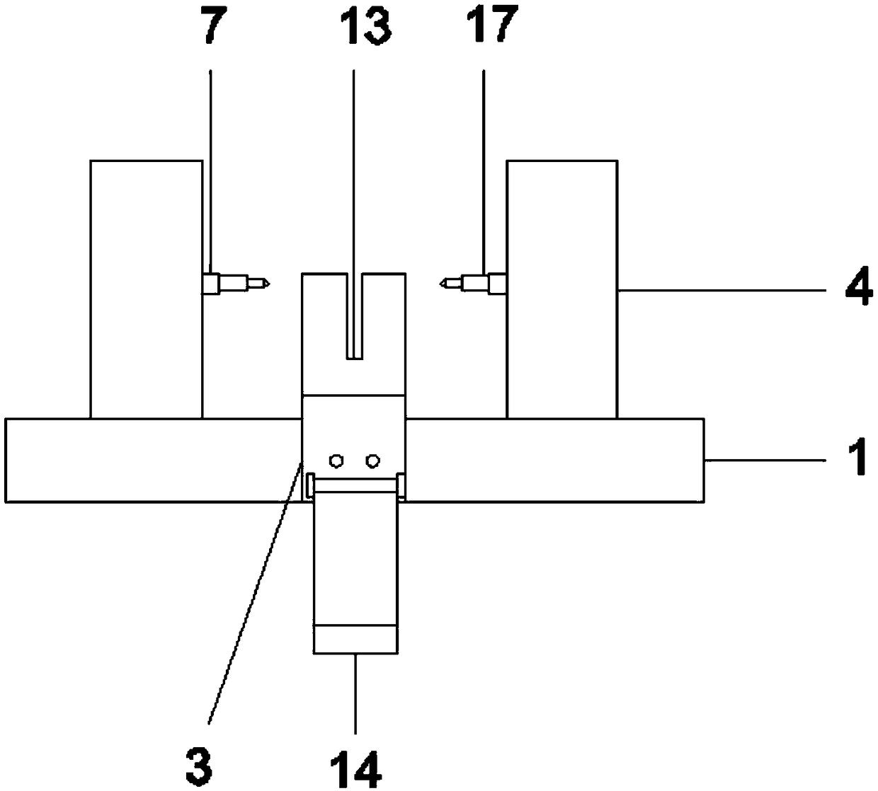
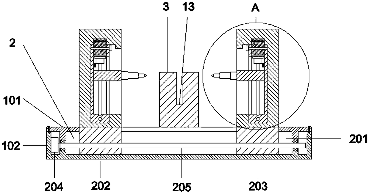
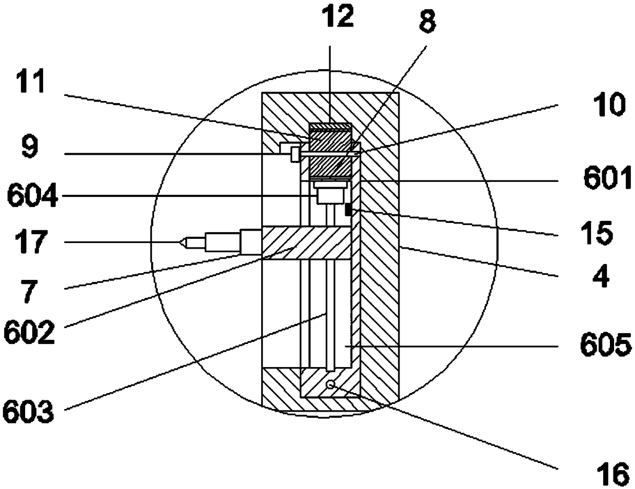
[0023] like Figure 1 to Figure 6 As shown, a chamfering device for an automobile chassis support frame includes a base 1, a sliding mechanism 2 is provided on the base 1, a clamping seat 3 is fixed in the middle of the base 1, and the left and right sides of the sliding mechanism 2 are fixed. A support 4 is symmetrically provided, and a chute 5 is arranged in the support 4, and a lifting mechanism 6 is slidably connected in the chute 5, and a rotating motor 7 is connected to the lifting mechanism 6, and the rotating motor 7 Drill rod 17 is installed on the output shaft, and the top of described elevating mechanism 6 is provided with groove 8, and the side of described elevating mechanism 6 is provided with motor 9, and rotating shaft 10 is connected in described groove 8, and described The rotating shaft 10 is connected to the output shaft of the motor 9, a gear 11 is fixedly installed on the rotating shaft 10, a toothed plate 12 is fixed on the top of the chute 5, the gear 1...

Embodiment 2

[0029] like Figure 1 to Figure 6As shown, a chamfering device for an automobile chassis support frame includes a base 1, a sliding mechanism 2 is provided on the base 1, a clamping seat 3 is fixed in the middle of the base 1, and the left and right sides of the sliding mechanism 2 are fixed. A support 4 is symmetrically provided, and a chute 5 is arranged in the support 4, and a lifting mechanism 6 is slidably connected in the chute 5, and a rotating motor 7 is connected to the lifting mechanism 6, and the rotating motor 7 Drill rod 17 is installed on the output shaft, and the top of described elevating mechanism 6 is provided with groove 8, and the side of described elevating mechanism 6 is provided with motor 9, and rotating shaft 10 is connected in described groove 8, and described The rotating shaft 10 is connected to the output shaft of the motor 9, a gear 11 is fixedly installed on the rotating shaft 10, a toothed plate 12 is fixed on the top of the chute 5, the gear 11...


PUM


Abstract

The invention discloses a chamfering device of an automobile chassis supporting frame and relates to the technical field of automobile manufacturing. The chamfering device comprises a base. The base is provided with a sliding and moving mechanism. The middle of the base is fixedly provided with a clamping base. Supports are symmetrically arranged on the sliding and moving mechanism leftwards and rightwards. The supports are internally provided with sliding grooves. The sliding grooves are internally connected with lifting mechanisms in a sliding manner. The lifting mechanisms are connected with rotating motors. Output shafts of the rotating motors are provided with drill rods. The chamfering device is simple in structure and convenient to operate, chamfering can be carried out on holes indifferent positions of the automobile chassis supporting frame, it does not need to repeatedly move the automobile chassis supporting frame, the production labor force is reduced, and the production efficiency is improved.

Description

technical field [0001] The invention relates to the technical field of automobile manufacturing, in particular to an automobile chassis support frame chamfering device. Background technique [0002] The car chassis is composed of four parts: transmission system, driving system, steering system and braking system. The function of the chassis is to support and install the automobile engine and its components and assemblies to form the overall shape of the automobile, and receive the power of the engine to make the automobile move and ensure normal driving. The automobile chassis support frame is a necessary accessory on the automobile. There are often through holes in different positions on the support frame. In the manufacturing process, it is generally necessary to chamfer both ends of the hole. At present, the commonly used processing method is to place the support frame on the support frame for chamfering. Due to the relatively low weight of the support frame and the larg...

Claims


Application Information

Patent Timeline
Patent Type & Authority Applications(China)
IPC IPC(8): B23B41/00
CPCB23B41/00
Inventor 徐杨徐克郎
Owner WUHU YUANSHAN MACHINERY MFG CO LTD
Why Eureka
Try Eureka